Carmen Mihai, Alexandra Gabriela Ene (2024). Advanced Numerical Simulations For Seakeeping Performance Analysis Of A Floating Architecture Based On Textile Structure. In: Human Factors in Design, Engineering, and Computing. AHFE Open Access, vol. 159, pp. 242–250. https://doi.org/10.54941/ahfe1005588
The paper presents the results of the seakeeping performances on the regular wave through advanced numerical simulations of a floating unit intended for the capture, storage and transport of hydrocarbons. The behavior of the floating unit in a frontal regular wave with a height of 0.6 m and a length of 5.3 m was investigated, at speeds of 0 and 2 knots, considering the 3 drafts corresponding to the cases of loading with 75%. The numerical tests were based on solving the RANS equations. For the qualitative investigation of the hydrodynamic characteristics of the flow in a regular wave, the free surface and the analyzed architecture were represented at different time steps for the stationary ship and at the speed of 2 knots. Based on the results of the short-term seakeeping analysis, to avoid complete immersion of the floating unit, the most significant restrictions on navigation with 75% hydrocarbon loading were determined.
Seen from another perspective, naval accidents that result in the spilling of a quantity of oil should not necessarily be considered a catastrophe, because hydrocarbons represent an extremely valuable raw material resource, which, through efficient processing, can be reintroduced into the economic value chain. In this context, the oil fractions can be collected by various means and transported from the spill site to specially arranged areas for the purpose of applying specific treatments for reprocessing (Choe et al., 2021).
The intervention procedure in case of an oil spill requires the following phases (Gerring et al., 2022):
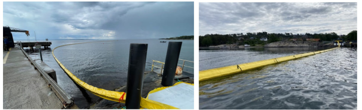
Spill limitation (with anti-oil dam) as it is presented in the Figure 1;
Mechanical recovery of spillage, with the help of skimmers.
Skimmers are devices that are almost always used in combination with dams. Depending on the quantity of the oil spill, the skimmers can be: stationary or mobile, self-propelled, operated from shore or by ships. The oil slick, previously delimited by means of dams, is selectively recovered,
Advanced Numerical Simulation for Seakeeping Performance Analysis 243
by absorption, with the help of skimmers and pumped into storage units on board ships or on the shore. Mechanical recovery does not affect the properties of the oil during collection and pumping, unlike the chemical and thermal processes that change the basic structure of the oil. Thus, the recovered oil can be reprocessed and reused (Choe et al., 2021).
Figure 1: Inflatable dams to limit the expansion of the oil bed.
Like dams, there is no single skimmer that can collect any type of oil spill and cope with rough sea conditions. Several factors must be considered before selecting skimmers, such as: i) the type of water where the oil spill occurred (seawater or fresh water); ii) the characteristics of the spilled oil (e.g. viscosity, potential degree of degradation over time); iii) the environmental conditions (e.g. wind speed, wave power, residue level, presence of seaweed ice, etc.) specific to the place where the accident occurred.
The performance of the skimmers decreases with the reduce of the thickness of the oil stain. Oil degradation is associated with undesirable phenomena that affect the proper functioning of the skimmers (decrease in the thickness of the oil stain, increase in viscosity until the coagulation of the degraded oil (Gâf-Deac et al., 2015).
Using advanced numerical analysis, the paper presents the results of a systematic study focused on the description of the composite floating unit for the storage of the mixture of water and hydrocarbons motions at the spill site, in regular waves.
MATERIALS AND METHODS
The analysis of the hydrodynamic performance of the floating unit was carried out based on a numerical study that included (Pacuraru et al., 2020; Burlacu et al., 2018):
the 3D modeling of the body (surface generation) of the floating unit made of composite material based on textile structure;
the weight estimation of the floating unit;
hydrostatic calculations and estimation of full load draft;
estimation of the traction power requirement;
regular wave seakeeping performance analysis and advanced numerical simulations (potential/viscous);
244 Mihai and Ene
calculation of the hydrodynamic response of the floating unit on regular wave.
The numerical analysis was oriented towards the systematic study on the description of the composite floating unit motions in regular waves (Bekhit et al., 2019; Bekhit et al., 2020).
The study was carried out using two different numerical approaches: the linear theory of sections based on the Lewis shape parametrization, developed by Domni¸soru, the in-house code DYN (OSC module - Oscillations) and, for a limited number of cases, the RANS method of viscous flow simulation using Fidelity FineMarine commercial code (Domnisoru et al., 2020).
The numerical test program included a series of CFD simulations to determine the still water resistance of the floating unit, considering speeds between 0.5 and 3 Kn and draft corresponding to 75% loading - water- hydrocarbon mixture. In addition, further calculations were performed to investigate the behavior of the floating unit in frontal regular wave (wave height of 0.6 m and wave length of 5.3 m) at speeds of 0 and 2 knots (Pacuraru et al., 2022; Mandru et al., 2022).
For the seakeeping analysis in regular waves based on the hydrodynamic potential formulation of the method of sections, the 75% loading of the structure and the range of wave pulsations between 0 and 15 rad/s were considered. Considering the symmetry of the floating unit geometry in relation to the diametral plane (CL), the floating unit - wave incidence angle was set in the range 0–180 degrees (step 5 degrees).
The speed during the seakeeping analysis of the floating unit had two values v = 0 and v = 2 knots (Kn), corresponding to the stopping and towing conditions of the floating unit. For the short-term formulation of the irregular wave, the ITTC standard spectral density function was used with the maximum significant height of the irregular waves of Hsmax = 2m, with the step Hs = 0.005 m, respectively 240 values (Hs = 0.050 – 2.000 m).
In all the analysed cases, the influence of the towing cable of the bow on the oscillations of the floating unit was neglected.
During the numerical simulations, the characteristics of the material and of the tested environment were considered, according to the data presented in Table 1.
Table 1. Characteristics of the composite of the floating unit and of the tested environment.
Table available in the original PDF paper.
Characteristic, U.M. Value Density of the swimmer material, g/cm3 1.421 Density of the floating unit body material, g/cm3 1.148 Density of filling material of the swimmer, g/cm3 0.020 Thickness - composite material of the swimmers, mm 1 Thickness - composite material of the floating unit body, mm 2 Maximum breaking force - composite material of the swimmers, daN/5 cm max. 400 (longitudinal); max. 380 (transversal)
(Continued)
Advanced Numerical Simulation for Seakeeping Performance Analysis 245
Table 1. Continued Characteristic, U.M. Value
Table available in the original PDF paper.
Maximum breaking force - composite material of the floating unit body, daN/5 cm
0.997
max. 900 (longitudinal); max. 800 (transversal) Mass - composite material of the swimmers, g/m2 900 Mass - composite material of the floating unit body, g/m2 2000 Density of brackish sea water (the fluid around the floating unit - Black Sea), g/m3
0.9313
Density of the water-hydrocarbon mixture (the fluid inside the floating unit), g/cm3 Speed, Kn 0-2
The main dimensions of the floating unit are presented in the Table 2.
Table 2. Constructive dimensions of floating unit.
Table available in the original PDF paper.
Dimension, U.M. Value Length, m 5.3 Maximum width, m 1.8 Unit draft, m 0,966 Height of the floating architecture, m 1.2 Displacement, m3 4.532 Wetted surface, m2 15.77 Speed interval, Kn 0-2
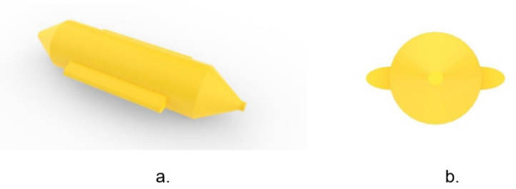
Figure 2 reveals the body of the floating unit, together with the two swimmers from the boards that were 3D modelled, the surface obtained being used as input data in all calculations performed.
Figure 2: Surface of the floating unit body used in the calculation (a. isometric view - left and b. front view - right).
RESULTS AND DISCUSIONS Based on the 3D surface of the floating unit body, the offset file used to describe the geometry in the calculation based on the section method was generated. The body of the floating unit was described by means of 531
246 Mihai and Ene
cross-sections (with 200 points on each section) along the entire length x = 0 stern and x = 5.30 m bow, for a length discretization step of δx = 0.01 m.
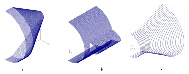
Figure 3 presents the details of the 3D shape plan of the floating unit required for the seakeeping analysis approach, in the section method formulation, under regular wave conditions.
Based on the geometric characteristics and the density of the materials, the weight of the empty body of the floating unit, without hydrocarbons, was estimated in the amount of 0.05289546 t.
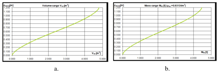
Figure 4 shows the volumetric curves for the hydrocarbon loading tank, where zHcfill [m] - the tank filling level; VHC [m3] - volume, MHC [t] - mass, density ρHC = 0.9313 t/m3.
For the seakeeping analysis of the floating unit, the loading case (75%) corresponding to the degree of filling of the tank on board the floating unit was selected, the draft being obtained based on the procedure of balancing the floating unit in calm water. The data are presented synthetically in Table 3.
Figure 3: Geometry description of the floating unit through cross-sections. a. sections x = 0.0-1.0, b. sections x = 3.0-4.0, sections x = 5.0-5.3.Figure 4: Volumetric curves for the hydrocarbon embarkation tank. a. VHC hydrocarbon volume curve [m3], b. MHC hydrocarbon mass curve [t].
Advanced Numerical Simulation for Seakeeping Performance Analysis 247
Table 3. Constructive dimensions of floating unit.
Table available in the original PDF paper.
Characteristic Description, UM Value
0.829438
Equation reproduced from the original PDF.
2.602315
VHC The volume of the hydrocarbons on board, m3 3.596192 MHC The mass of the hydrocarbons on board, t 3.349134 xHC The position of the gravity center of the hydrocarbon mass on board, m
0.000000
yHC The position of the gravity center of the hydrocarbon mass on board, m
0.474026
zHC The position of the gravity center of the hydrocarbon mass on board, m
0.727345
V The volume of the submerged hull, m3 3.412266 1 The displacement of the floating unit, t 3.402029 Taft The draft at the stern, m 0.727389 Tfore The draft at the bow, m 0.727300 Tmid The medium draft from the calm water balance of the floating unit
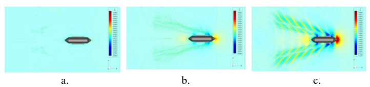
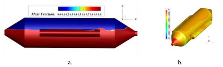
Figure 5 shows the topology of the free surface for speeds of 0.5 Kn; 2 Kn and 3 Kn, and in Figure 6, the wetted surface for the maximum speed analyzed, as well as the pressure distribution on the body of the floating unit.
Figure 5: Topology of the free surface represented for a. v = 0.5 Kn, b. v = 2 Kn; c. v = 3 KN. Charge case 75%.Figure 6: a. Wetted surface at v = 3Kn, b. Pressure distribution on the body of the floating unit.
248 Mihai and Ene
The regular wave seakeeping analysis highlights the following:
- the weight estimation of the floating unit and the hydrostatic calculations enabled the evaluation of the 75% loading case of the floating unit depending on the degree of filling of the tank and the related drafts; - the main navigational restrictions are registered mainly from the criteria formulated for the combined movements in the vertical direction and the pitching movement due to the limitations generated by the construction height of the floating unit (H = 1.2m) to avoid its complete immersion, for both speed cases (v = 0; 2 Kn). In the case of v = 2 Kn the increase in pitch oscillation acceleration contributes to the navigational restrictions imposed on the floating unit. At 75% load the rolling motion and acceleration contribute to navigational restrictions for the floating unit; - the inclusion of an additional separation membrane in the diametral plane (CL) of the floating unit coud have a significant effect on its transverse stability, but for the short-term dynamic response to seakeeping the effect will be reduced; - it is obvious that in the case of maximum load (100%), in which the floating unit can carry a quantity of 4.47 t of mixture of water and hydrocarbons, the average draft is 0.966 m which leads to a freeboard of 0.234 m. The rounded shapes above the waterline do not provide the prerequisites for a significant buoyancy reserve and floating area. Moreover, the hull and the gravity center positions lead to poor initial transverse stability under full load.
CONCLUSION
Based on the results of the short-term seakeeping analysis, the most significant navigation restrictions are recorded at the traction speed v = 2Nd, regular encounter waves (µ = 180 deg) in the cases of 0% and 100% hydrocarbon loading, without and fully loaded with hydrocarbons, mainly due to the seakeeping criteria for the combined vertical movement, namely movement and pitch acceleration, to avoid complete immersion of the floating unit.
For the intermediate case of 75% loading, the limits of navigation conditions at the traction speed of v = 2Nd are Hslimit = 0.251–1.250m, Blimit = 0.23–2.07.
It is recommended to operate the floating unit, at the towing speed of v = 2Nd, in relatively calm sea conditions (Hs = 0.25m).
Exceeding the limits imposed by the seakeeping criteria will lead to the immersion of the floating unit and with a higher acceleration field above the cumulative values (combined vertical, pitch and roll) of 0.40– 0.45 g (g = 9.81m/s2) in the vertical direction at the extremities floating unit.
Advanced Numerical Simulation for Seakeeping Performance Analysis 249
Given the fact that the freeboard remaining in the case of full load is very reduced, with an effect on the buoyancy reserve, there is a risk that the floating unit will sink under certain operating conditions. In this case, the tow line can reach the propeller area, which could lead to damage to the propellers. A solution to improve performance would be to change the diameter of the swimmer’s boards, to increase the buoyancy and directly the freeboard.
ACKNOWLEDGMENT
This scientific paper is funded by the Ministry of Research, Innovation, Digitalisation within Program 1 - Development of the national RD system, Subprogram 1.2 - Institutional Performance - RDI excellence funding projects, Contract no. 4PFE/2021 and is the result of the collaboration with Naval Architecture Research Center, Gala¸ti, Romania.
REFERENCES
Bekhit, A.; Lungu, A., (2019) “Numerical Simulation for Predicting Ship Resistance and Vertical Motions in Regular Head Waves”, ASME 2019. In Proceedings of the 38th International Conference on Ocean, Offshore and Arctic Engineering, Glasgow, Scotland, 9–14 June 2019. Bekhit, A., Obreja D., (2020), “Numerical and Experimental Investigation on the
Free-surface Flow and Total Resistance of the DTMB Surface Combatan”t, IOP Conf. Ser.: Mater. Sci. Eng. 916 012008. Burlacu, E.; Domnisoru, L.; Obreja, D., (2018), “Seakeeping prediction of a survey vessel operating in the Caspian Sea”, ASME: Proc. 37th International Conference on Offshore Mechanics and Arctic Engineering (Madrid, Spain, 17–22 June 2018) OMAE 2018–77126. Choe, Y.; Lee, J.; Jung, W.; Park, J.; Jho, J. Y., et al.; (2021) “Gravity-
based oil spill remediation using reduced graphene oxide/LDPE sheet for both light and heavy oils”. Process Safety and Environmental Protection, Vol. 156, pp. 617–624. Domni¸soru, L., (2020), “On the oscillations response prediction of a small liquid petroleum gas carrier in random oblique waves”, ModTech 8th International Conference, Maritime Engineering and Navigation, 24–27 June 2020, Constanta, IOP Conference Series: Materials Science and Engineering, Vol. 961, Issue 1, ISSN: 1757-899X, Paper ID: G-22, https://iopscience.iop.org/article/10.1088/ 1757-899X/916/1/012028 Gâf-Deac, I. I., et al., (2015) “New development: from linear to nonlinear economy.
Challenges from the perspective of sustainable development”, - W.1, Romania’s Sustainable Economic and Social Development. Models, Scenarios, Evaluations, The Romanian Academy, The 3rd Intl. Economic Scientific Research – Theoretical, Empirical and Practical Approaches, ESPERA 2015, ISBN 978-3-631-67330-0, E- ISBN 978-3-653-06571-8, E-ISBN 978-3-631-69664, E-ISBN 978-3-631-69665- 1, doi: 10.3726/978-3-653-06571-8. Gerring, S.; Hu, G.; Li, J.; Hewage, K.; Sadiq, R.; (2022)” Evaluation of offshore oil spill response waste management strategies: A lifecycle assessment-based framework”, Journal of Hazardous Materials, Vol. 432, 128659.
250 Mihai and Ene
Mandru, A.; Rusu, L.; Pacuraru, F., (2022) “Hydrodynamics performance prediction of full-scale ship”, International Journal of Modern Manufacturing Technologies, https://doi.org/ 10.54684/ijmmt.2022.14.3.130 Pacuraru, F.; Domnisoru, L.; Pacuraru, S., (2020) “On the comparative seakeeping
analysis of the full - scale KCS by several hydrodynamic approaches”, JMSE Journal of Marine Science and Engineering, (https://www.mdpi.com/journal/jmse; https://www.mdpi.com/2077-1312/8/12/962), Volume 8, Issue 12, Paper No. 962, (ISSN 2077-1312), pp. 1–32, Basel (Switzerland), December 2020, MDPI Multidisciplinary Digital Publishing Institute - Academic Open Access Publishing. Pacuraru, F.; Mandru, A.; Bekhit, A., (2022) “CFD Study on Hydrodynamic Performances of a Planing Hull”. Journal of Marine Science and Engineering. Vol. 10(10):1523. https://doi.org/10.3390/jmse10101523
LISTED IN THE AHFE DIGITAL BOOKSTORE CATALOGUE
Explore the complete digital volume
Human Factors in Design, Engineering, and Computing
Read this individual research paper free through the original publisher, or explore the full digital proceedings book.
ISBN 978-1-964867-35-9
Explore this ISBN in the AHFE Bookstore ↗Listed in the July 2026 bookstore catalogue; search by ISBN to confirm current availability · Digital book purchase optional