Afonso Santos, Álvaro M. Sampaio, Artur Costa, António J. Pontes (2024). Design and development of urban space products by Large-scale robotic extrusion-based additive manufacturing technology. In: Human Aspects of Advanced Manufacturing, Production Management and Process Control. AHFE Open Access, vol. 146, pp. 163–170. https://doi.org/10.54941/ahfe1005162
The production of products in additive manufacturing systems through the extrusion of material using robotic arms requires new paradigms ranging from product design, material selection, material processability, communication with the production system, production control, etc. The development of products through these technologies allows the production of solutions of considerable scale and innovation. These applications have been studied, especially for outdoor spaces, precisely because of the scale that production with robotic arms allows. Green areas within urban spaces are one of these outdoor spaces, which provide space for leisure and recreation, which leads to social improvements by gathering people. In this context, this research seeks to create products that improve social interaction within urban green spaces. To achieve this, sustainable products will be developed, through a large-scale robotic extrusion-based system, combining the versatility and design possibilities that additive manufacturing allows, with the associated sustainability of recycled plastic waste. Thus, this paper proposes a methodology for validating recycled materials and to understand the limitations that the material brings to the parametric models created and the challenges for production. For that, two sample-parts were developed. One part allowed to understand the maximum printing angle, and the other provided an understanding of the behavior of the material when the part had corners with different curvatures. Finally, an outdoor product to be placed in the urban space was developed and produced with the production parameters studied.
The growth of urban areas and the increase in the population living in them has led to a greater distancing of its inhabitants from nature, which poses a risk to their health (WHO, 2017). Green spaces within urban areas play a fundamental role in the quality of life of its inhabitants, bringing bene- fits not only to the environment but also to individual and general health
of the population (Hartig et al., 2014; WHO, 2016). It is therefore impor- tant to create new spaces or maintain existing green spaces (WHO, 2017). As such, the opportunity arises to create areas for socializing and studying outdoors, creating social interactions in a more natural and stimulating envi- ronment, which is essential for the well-being and performance of users. The aim of this work is to better understand how product design can improve the quality of urban spaces by using the large-scale additive manufacturing process to produce a product in this context. Currently, additive manufac- turing processes can be divided into several technologies, each more suited to a particular area. This work explores the use of a robotic arm in large- scale additive manufacturing, with the extrusion of plastic material derived from recycled urban waste, namely recycled polypropylene (PP). The use of robots in additive manufacturing is a recent concept, but it has been grow- ing in recent years (Roschli et al., 2019; Serrano and Bares, 2023). Some of the main objectives include understanding how the technology works, how it is programmed and the limitations it offers in the production of parts. The development of a product to be produced using robotic extrusion will allow to study the feasibility of this technology. To do this, first it was necessary to develop two sample-parts with specific characteristics to assess the maxi- mum printing angle (overhang) and the variability of curvature radii that the product would be able to assume so it could be correctly printed and used as a proof of concept.
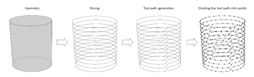
PREPARING A PROGRAM FILE – FROM A 3D MODEL TO A KRL CODE First, it is important to understand the process in which a CAD model becomes a code that can be read by the robot controller. For this study a KUKA Robot was used and, as such, the programming language employed was KRL (Kuka Robot Language). For visual programming, Grasshopper software was used, which is the parametric environment of Rhinoceros, using the add-on KUKA|prc to simulate the robot movements in a virtual environ- ment and to export the printing code. A Grasshopper program was developed to transform a geometry into a continuous path that the TCP (Tool Control Point) of the robot end effector must follow. Figure 1 shows a schematic of how this program works. Primitive Grasshopper components were used to generate the toolpath and turn it into a set of ordered points that will rep- resent the robot commands for its movement. For the slicing process of the geometry, we used the contour command. Subsequently, through a set of command groups, or clusters, the continuous path is generated. This path is then divided into points, which in turn will originate planes that contain all the necessary information for the robot’s movement.
The orientation of these planes is what defines the tool orientation itself. Once the planes are defined, they are the input commands for KUKA|prc. Within the plug-in we can define the robot end effector’s initial and final positions, as well as the robot speed (Cuevas and Pugliese, 2020).
Design and Development of Urban Space Products by Large-Scale Robotic Extrusion 165
Figure 1: Process of transforming a geometry into Kuka PRC commands.
Software Limitations When programming, several limitations may be encountered in the develop- ment and production of the part. Many of these limitations also derive from hardware constraints such as ineffective on-line communication between robot and extruder. Since there is no control of the extruder by the robot’s controller, there is no dynamic relation between the movement of the robot and the extruded material. This restricts, for example, the fabrication of cavi- ties and other discontinuities in the physical structure of the printed product. Thus, the framework of the part is limited by the programming and hardware capabilities of the robotic fabrication system, confining it to just a profile part with a continuous path. The production of infills may be possible, but it is important to define a specific toolpath pattern depending on the type of geometry of the part, so it can be properly generated. With these constraints, making closed parts (caping) is also challenging, therefore, it is only possible to make open parts at the base and top.
Another consideration is the extruded material width. All the parts devel- oped in this study, were produced with a 4 millimeter nozzle. Having said that, the use of a fixed layer height of 3 millimeters resulted in an 8 millime- ter layer width, caused by the material’s inherent fluidity. So, when designing a sample-part, the CAD model must not contain boundary sections closer than that distance, to not overlap each other.
PRINTING PARAMETERS AND DESIGN GUIDELINES As aforementioned, it is important to understand the software and pro- gramming limitations when designing. Moreover, there are physical design constraints to factor in as well. In this study, a methodology was developed with the ability of validating different materials for large-scale additive man- ufacturing processes. To do so, two parts were developed wherefrom it is possible to draw various conclusions regarding the design guidelines. One part provides inferences with respect to the overhang angle, another studies the variation in curvature of closed corners and bridging.
Overhang Angle As a point of reference, the overhang angle considered herein refers to the deviation of a layer contour from the vertical build direction relative to a horizontal plane. This crucial overhang angle is used as a criterion to deter- mine whether a part is suitable for additive manufacturing (Roschli et al., 2019; Isa, Yi˘git and Lazo˘glu, 2018). For example, a straight cylinder will
have an overhang angle of 0
, but if the top is caped, that top will have an overhang angle of 90
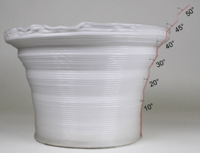
. This approach of measuring angles allows for better simulation of CAD models using draft analysis software. The maximum over- hang angle is an important factor to consider when designing for large-scale additive manufacturing, since it was not feasible to produce support mate- rial with the means at our disposal. To test the referred maximum overhang angle, the part shown in Figure 2 was produced.
Figure 2: Resulting first sample-part at different angles with section delineation of each expected angle outcome.
This consists of a cylindrical base, since a circular shape provides better results in terms of adhesion to the print base and less warping. Sections of increasing angles were printed along the build direction. The part starts at 0
then subsequent angles are introduced in the following order: 10
; 20
; 30
; 45
, and 50
. The results were consistent with the CAD model up to the 30
mark, however, further printed layers started to sag and collapse before reaching the 40
angle. This is consistent with the fact that features with an inclination exceeding an angle of 45
typically require support (Isa, Yi˘git and Lazo˘glu, 2018).
Corners and Bridging In the following sample-part, two types of tests occur: one allows to under- stand the minimum curvature of a closed corner and the other evaluates the material behavior when bridging takes place.
In order to achieve a seamless and uninterrupted motion along toolpaths with sharp corners, the majority of computer numerical control (CNC) systems employ a local smoothing technique. This involves the use of a pre- defined curve or spline to soften corners, allowing the system to slow down and adjust the feed direction within the constraints of machine kinematics. If sharp corners are in close proximity, the path speed is significantly decreased to enhance accuracy (Tajima and Sencer, 2017). This principle can be applied to a robotic arm. Considering that the extrusion rate is constant during a layer print, it is expected to achieve material accumulation in sharp corners (due
Design and Development of Urban Space Products by Large-Scale Robotic Extrusion 167
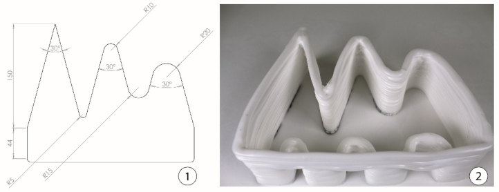
to robot speed also being constant). Referring to the part shown in Figure 3, we can analyze the minimum curvature radius of a corner that can be printed without material overlap.
Figure 3: Top view of the second sample-part (1) with the dimensions of the corner angles and their curvature radius (2). Dimensions in millimeters.
One side of the part consists in three consecutive triangles that end in a closed rectangle-like shape. The intersections of these triangles result in a total of five corners with a 30
angle. That said, different curvature radii were assigned to the respective vertices, with the first vertex having no curvature at all. The remaining vertices have a radius of curvature of 5 millimeters, 10 millimeters, 15 millimeters and 20 millimeters (observing the part from left to right). The corners with a radius of 15 millimeters and 20 millimeters present fewer imperfections created by accumulated material, when compared to the previous three with considerable material overlap.
The other side of the sample-part aims to analyze the effect of bridging, which is a phenomenon that occurs when a horizontal layer is printed, with- out a support or bottom layer, between two foundations. The propensity is for the material to flow out, not maintaining the desired shape. Despite the high deformation of the bridge layer, the subsequent deposited layers tended to level out as construction progressed.
PRODUCT DEVELOPMENT Once the design guidelines for the production of parts using this additive manufacturing process were defined, a product was developed with the inten- tion of understanding the maximum dimensions capacity of the technology. The part was produced with a layer height of 3 millimeters. The temperatures of the extruder heating zones were as follows: 160
C for zone 1; 170
C for zone 2; 180
C for zone 3; and 185
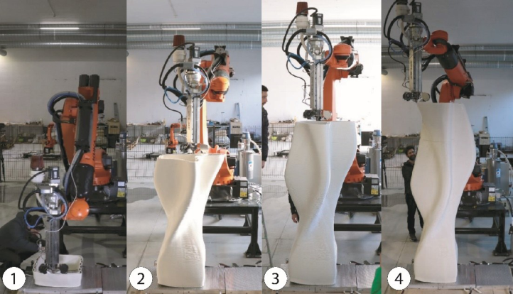
C for zone 4. The latter heating zone is closest to the nozzle, of which temperature corresponds to the processing temperature of the recycled PP printing material. The total production time was 26 hours and 30 minutes. Around 100kg of PP pellets was used to pro- duce the part. The developed product consists of a public bench that was printed vertically at 2.70 meters high. Figure 4 shows four different stages
of production. Stage one (1) represents the initial production hour, during which it is crucial to prioritize the adhesion of the first layers to the print- ing base. Stages two (2) and three (3) mark a mid-point in production where adjustments to printing parameters are made between each stage. Stage four (4) signifies the culmination of the process, resulting in the final part that needs to be detached from the printing base for subsequent installation in an urban space.
Figure 4: Different production stages of the developed bench shape.
The production process went according to plan, and it was possible to produce the part in its entirety. However, some minor issues occurred, mostly due to the inherent crystallinity of the material. The first setback concerned the poor adhesion of the first layer to the printing base, which occurred at the start of the process, causing slight warpage. This was limited to only one edge of the printed layer, so it didn’t cause any critical problems in the overall production. The warpage was due to poor deposition of the material on the printing base, which did not fill the fixing gaps to a full extent. Regarding the succeeding construction sections, it yielded consistent layer height through- out the build orientation, by complying with the previously specified design constraints.
The additive manufacturing production of large-scale furniture recycled from urban waste, such as the one exhibited, arose from the need to quickly place products and materials in urban spaces with mechanical and functional characteristics close to those obtained with definitive production processes. This helps answering the needs related to sustainability, such as waste reduc- tion or elimination, reduction of the carbon footprint, societal needs, among others. The resulting product is a bench made of recycled plastic material that was shredded, grinded and compounded in the form of pellets, to be placed horizontally in an urban space. The utilized production process proved to be
Design and Development of Urban Space Products by Large-Scale Robotic Extrusion 169
advantageous, considering that some of its benefits are the design freedom (despite the mentioned constraints) and the use of less material, compared to other production processes for large parts, making it more sustainable and eco-friendlier.
Lastly, the design of this eco-efficient model made it possible to demon- strate that this technology can be tailor-made to process the minimum amount of plastic material necessary for it to be structurally sound for public use. Also, since the equipment and products have a low energy consumption aspect, it is not necessary to spend a large amount of energy to optimize the manufacturing process, both in terms of materials (low consumption in the fusion of raw materials) and of the electrically powered equipment itself.
CONCLUSION
The development of urban space products, particularly, a large dimension bench, was attained with a large-scale additive manufacturing technology, consisting of material extrusion using a robotic arm. This innovative and dis- ruptive new product design will help promote social interactions, while also improving green areas within urban spaces, due to the added sustainability of its recycled-based plastic waste material. It was concluded that recycled virgin PP was the most suitable material for the manufacturing of the case study since it has sufficient structural integrity and mechanical resilience and a significant capacity to withstand the effects of consecutive human interac- tion. A methodology was initially devised to discern the design constraints and process limitations to produce recycled materials. The development of two sample-parts helped determine the maximum printing angle of 30
and the maximum curvature radius must be equal to or greater than 15 millime- ters. This resulted in a disruptive and lightweight form, compared to similar existing parts, 2.70 meters wide, and with the purpose of being an outdoor product to be placed in urban spaces for social gathering.
ACKNOWLEDGMENT
This work was carried out within the framework of the “Agendas para a Inovação Empresarial” (Project n
49, acronym “INOV.AM”), supported by the RRP – Recovery and Resilience Plan and by the European Funds NextGeneration EU. http://recuperarportugal.gov.pt/
REFERENCES
Cuevas, D. and Pugliese, G. (2020) Advanced 3D printing with grasshopper: Clay and FDM. Hartig, T., Mitchell, R., De Vries, S., and Frumkin, H. (2014) “Nature and health”,
Annual Review of Public Health, 35(1), pp. 207–228. Isa, M. A., Yi˘git, I. E. and Lazo˘glu, ˙I. (2018) “Analysis of Build Direction in Deposition-Based Additive Manufacturing of Overhang Structures”, proceedings of the 29th Annual International Solid Freeform Fabrication Symposium. Roschli, A., Gaul, K. T., Boulger, A. M., Post, B. K., Chesser, P. C., Love, L. J., Blue, F.,
and Borish, M. (2019) “Designing for big area additive manufacturing”, Additive Manufacturing, 25, pp. 275–285.
Serrano, A. N. and Bares, J. M. E. (2023) Advances in Large-Scale Robotic 3D Printing with Plastic Pellets. Tajima, S. and Sencer, B. (2017) “Global tool-path smoothing for CNC machine
tools with uninterrupted acceleration”, International Journal of Machine Tools & Manufacture, 121, pp. 81–95. World Health Organization (WHO) (2016) Urban green spaces and health (No.
WHO/EURO: 2016-3352-43111-60341). World Health Organization, Regional Office for Europe: Copenhagen, Denmark. World Health Organization (WHO) (2017) Urban green spaces: A brief for action.
World Health Organization, Regional Office for Europe: Copenhagen, Denmark.
LISTED IN THE AHFE DIGITAL BOOKSTORE CATALOGUE
Explore the complete digital volume
Human Aspects of Advanced Manufacturing, Production Management and Process Control
Read this individual research paper free through the original publisher, or explore the full digital proceedings book.
ISBN 978-1-964867-22-9
Explore this ISBN in the AHFE Bookstore ↗Listed in the July 2026 bookstore catalogue; search by ISBN to confirm current availability · Digital book purchase optional