Yang Zeng, Xiaojun Liu, Jindan Feng, Jinshan Liu, Yang Yi (2023). Automatic generation technology of dimension chain considering assembly characteristics. In: Human Aspects of Advanced Manufacturing. AHFE Open Access, vol. 80, pp. 207–217. https://doi.org/10.54941/ahfe1003523
Aiming at the deviation transfer path problem in assembly tolerance analysis, a method of automatically searching the assembly dimension chain is proposed, which first uses various types of information units to express the key information required for dimension chain generation, establishes the assembly accuracy information model, constructs the part order constraint association matrix and tolerance feature association matrix on the basis of considering the multiple assembly order and multiple parallel constraints in the actual assembly process, and generate assembly relationship transfer diagram. At the same time, the traditional shortest path algorithm is optimized by using the small root stack structure in combination with the transfer diagram application scenario, and the assembly dimension chain is obtained by local search of the transfer diagram according to the assembly order and the customized constraint selection rules. Based on the Qt application development framework and the OpenCASCADE graphics library, the prototype system is developed and verified, proving that the method can effectively improve the efficiency of the automatic dimensional chain search, and the generated dimensional chains are more consistent with the actual assembly process planning.
Product assembly deviation analysis technology is to take various types of geometric accuracy of products as the target, consider part design tolera- nce, assembly constraint relationship, assembly sequence and other factors, use computer simulation technology to carry out error transmission, accu- mulation and coupling analysis of each link, and use it as a guide for assembly accuracy control. The primary problem of product assembly devi- ation analysis technology is to determine the route of error transmission according to the assembly function requirements, where the widely used solu- tion is the automatic search algorithm based on the assembly dimensional chain.
Huang Mifa et al. (2022) used SWRL to describe inference rules to derive the dimensional chain with the smallest and shortest assembly constraint
deviation. Zhang Z et al. (2017) proposed an algorithm for automatic gene- ration of dimensional chains based on geometric tolerances and assembly constraints by intersecting the actual constraint directions of different refe- rence relations to perform a multi-branch propagation path search. Zhenbo G et al. (2016) used the attribute set of features to represent the partial of information and their relationship information to generate inter-feature tran- smission networks for searching and extracting assembly dimension chains. Zheng Sujuan et al. (2017) established the assembly constraint association matrix of the main dimensional chain and the auxiliary dimensional chain based on the different assembly positioning constraints between parts, and realized the automatic generation of dimensional chains through the shortest path and the automatic search of key features. Gao Z et al. (2015) propo- sed the generation rules of dimensional chains and the generation method of generating VGC (Variational Geometric Constraint) network based on VGC theory. Wang P et al. (2014) used database technology to manage assembly information and automatically generated 3D assembly dimensional chains by searching for assembly constraints and their dependencies and related dimensional locations in the database. Zhou Jiangqi et al. (2005) establi- shed the body assembly contact chain model based on the study of assembly directed graph representation, and generated the body assembly dimensional chain by mapping the relationship between feasible paths and dimensional chains. Guo Chongying et al. (2014) established the geometric tolerance fea- ture matrix and the assembly feature association matrix and generated the assembly directed graph, searched after eliminating irrelevant vertices and edges, and finally determined the assembly dimension chain by the shortest path principle. Bao Qiangwei et al. (2016) established dimension and tolera- nce and assembly constraint information units on the basis of standardizing and improving tolerance information, and constructed assembly relationship transfer diagram according to the correlation of geometric features of the assembly, and finally achieved automatic generation of assembly dimension chain on the basis of considering the search priority. Wang H et al. (2006) established the closed vector diagram of dimensions by analyzing the part instantiation definition information and performance feature definition infor- mation, and finally obtained the three-dimensional closed dimensional chain. Rikard SDerberg et al. (1999) proposed a geometry-based constraint-based assembly tolerance chain analysis method to establish assembly dimension chains by analyzing the occurrence of geometric coupling in different levels of assembly models.
This paper proposes an automatic dimensional chain generation technique based on previous research that takes into account the assembly characteri- stics and the comprehensive influence of various tolerances, and the general idea of the method is as follows: 1) parsing the assembly model file to esta- blish an accuracy information model, including the construction of various information units to describe the tolerances and functional requirements of the assembly, and at the same time defining the constraint priority rules in the case of parallel assembly constraints; 2) establishing The assembly process
Automatic Generation Technology 209
tree reflects the assembly hierarchy and the assembly order of parts, extracts all kinds of associated features in the information unit, constructs the part order constraint association matrix and tolerance feature association matrix in combination with the assembly order, and generates the assembly relati- onship transfer diagram; 3) optimizes the shortest path algorithm using the small root pile structure, considers the assembly order and the customized constraint selection rules to conduct local search on the assembly relation- ship transfer diagram, and realizes the automatic generation of the assembly dimensional chains.
MODELING OF ASSEMBLY ACCURACY INFORMATION An assembly accuracy information model is generally a digital representa- tion method that consists of multiple data structures inside a computer to describe and store the influence factors related to product assembly accuracy. In the paper “Technology of automatic generation and update of assembly dimension chain for assembly process” by Renchao Zhang et al. (2020), the authors express the assembly model information such as dimensions, tole- rances and assembly constraints by constructing information units such as dimensional tolerance unit UDT and assembly constraint unit UAC. On this basis, in this paper, in order to more completely express the geometric tolera- nces and measurement requirements that affect the final assembly accuracy of the product, the data structure models of geometric tolerance unit and measu- rement requirement unit are established separately, which can fully consider the situation of multiple geometric tolerances and multiple assembly functio- nal requirements, and at the same time, a new assembly constraint unit search rule is proposed for the case of parallel assembly constraints between two parts, in order to meet the functional requirements of the automatic search of the assembly dimensional chain, and lay the foundation for the subsequent automatic generation of the dimensional chain.
Geometric tolerance unit expresses all information about a single geome- tric tolerance within a single part. The geometric tolerance unit is represented by UGT, including tolerance type Gt, tolerance id, tolerance belonging to the part Pow, tolerance associated objects O1, O2, tolerance value V, tolerance field type TA, whose general expression is shown below: UGT = {Gt, id, Pow, O1, O2, V, TA} (1)
where, the tolerance type Gt is mainly divided into flatness, parallelism, coa- xiality, position, etc.; tolerance id is the serial number of the tolerance unit in the list of geometric tolerance units; Pow is the part to which the tolerance belongs; the associated objects O1, O2 are the positioning features and the corresponding datum features directly selected during the tolerance marking. For shape tolerances, such as flatness, cylindricity, etc., the datum feature is the same as the positioning feature. For some geometric tolerances, such as position degree, there may be more than one datum feature, and the default datum feature is the first datum; the tolerance value V is the tolerance design size; TA represents the tolerance domain type, such as parallel interplanar area, cylindrical surface area, etc.
The measurement operation is performed to specify the key features that need to meet the final functional requirements and to obtain a comparison of the deviations before and after the analysis. The measurement requirement unit is represented by UMR and includes measurement type Mt, measurement id, measurement associated features O1, O2, part Pow to which the measure- ment feature belongs, measurement direction vector Vec, and measurement value V. The general representation is shown as follows: UMR = {Mt, id, O1, Pow1, O2, P0w2, Vec, V} (2)
where, measurement type Mt is divided into point-to-point, point-to-face, line-to-line, line-to-face, face-to-face, etc.; id is the serial number of the measurement unit in the list of measurement requirement units; associated features O1, O2 are the geometric elements directly selected during the mea- surement operation; measurement direction vector Vec is the direction vector of the measured distance, which can be obtained by measuring geometric information such as coordinates, directions and normals of geometric ele- ments; the measured value V is the distance size obtained by mathematical calculation.
In the actual assembly process, it is necessary to assemble the object part to the target part, and according to the “3-2-1” positioning principle, it is often necessary to define multiple assembly constraints to make the object part complete deterministic positioning, which means that there may be mul- tiple assembly constraint units between two parts, and the dimensional chain search process encounters such parallel constraints because of the search dire- ction can not be determined often difficult to continue or a large number of repeated search. Therefore, we propose an effective constraint selection rule, which can determine the search priority of assembly constraint units in the assembly relationship transfer diagram, and the search efficiency can be significantly improved by prioritizing the assembly constraint units with high priority. We classify the assembly constraints into two major categories according to the contact relations:
1) Cases with actual contact between constraint-related features, such as face-to-face fit, shaft-hole interference fit, spherical interference fit, tape- red interference fit, etc. In this case, the geometric features have solid contact with each other, and the increase in the effective constraint area can improve the accuracy and stability of the assembly positioning and reduce the deviation of the mating surface of the part relative to the ideal position. 2) Constraint-related features do not have actual contact with each other or exist only in the limit position, such as face-to-face alignment, face-to- face parallelism, axis parallelism, axial hole clearance or transition fit, spherical clearance or transition fit, tapered clearance or transition fit. In this case, the geometric features do not have solid contact with each other. Compared with the ideal state, the deviation of the fit between the geometric features is influenced by the combined effect of the surface machining quality of the part and the positioning deviation during the assembly process, and the deviation is greater than that in the case of first fit.
Automatic Generation Technology 211
Let the area of the two geometric features associated with the assembly constraint be S1 and S2, and define the constraint area S = min(S1, S2), where the value of S is 0 for the second type of constraint that does not have actual contact. the sequence of assembly operations for assembling the object part to the target part generally includes the first matching condition, the second matching condition, the third matching condition, etc. In order to reduce the introduction of fit deviations to the parts in the dimensional chain For the case of multiple first assembly constraints between two parts, the assembly constraint with the larger S value is used as the priority matching condition; if the S value is the same as 0, firstly, the assembly constraint with the smaller distance is matched first, and secondly, the fixed fit is matched first than the drift fit, so the priority order in the second class constraints is face-to-face alignment > all kinds of transition fits > all kinds of gap fits > face-to-face parallelism > axis parallelism.
AUTOMTIC GENERATION OF ASSEMBLY RELATIONSHIP TRANSFER DIAGRAMS The assembly model consists of sub-assemblies or parts assembled in a certain order, and it is necessary to use a suitable structure to express the assembly order and sub-assembly relationships of the parts. Currently, the widely used method is to express the assembly hierarchy and assembly order within the assembly using bracketed strings, but this expression method has the problem that it is difficult for the computer to recognize and modify the sub-assembly relationship and order of the strings, which can be effectively avoided by using the assembly process tree in this paper. The assembly process tree is an ordered tree with a clear structure, and the insertion, deletion, and order adjustment of process nodes are very convenient. Each assembly process node Si is executed in left-to-right order according to its subordinate sub-nodes, and sub-assembly processes at different levels are executed in bottom-up order, reflecting the entire assembly process from part assembly to final assembly.
The assembly process tree can be understood as a N-fork tree, which is tra- versed posteriorly, and the access order of the nodes represents the assembly order of each component.
The assembly constraints represent the association relationship between each part. By traversing the assembly process tree to obtain the sequence of part assembly order, the assembly constraint unit information is resolved, and the constraint association matrix C(i, j) is constructed according to the part assembly order, where the serial numbers i and j represent the parts corresponding to the assembly order values. Since there may be parallel con- straints between parts, the matrix entry Cij represents the set of assembly constraint unit ids representing the constraint relationship between part i and part j. When Cij = 8, it means there is no constraint association relationship between part i and part j; when Cij̸ = 8, it means there is a constraint associ- ation relationship between part i and part j. Since the constraint relationship between parts is mutual, we have Cij = Cji. The general form of C(i, j) is as follows:
part1 part2 part3 ... partn [Equation or mathematical symbol available in the original paper PDF][Equation or mathematical symbol available in the original paper PDF] part1 part2 part3
C(i, j) =
(3)
Equations and mathematical formulas are available in the original paper PDF.
All dimensional tolerance units as well as geometric tolerance units inside each part are retrieved in turn, and the two associated objects O1 and O2 of the tolerance units are extracted, and all object features are mapped with unique feature ids.
The initial values of the elements of the tolerance feature association matrix D(i, j) are all (0, 0), which means that there is neither dimensional tolerance nor geometric tolerance association between all features. The fea- ture id of the associated object O1 in the tolerance unit is defined as row i of the matrix, and the feature id of the associated object O2 is defined as column j of the matrix, (dimensional tolerance unit id, geometric tolerance unit id) is then used as matrix item Dij. The value of Dij is (a, b), if a>0 and b>0, it means that feature i and j have both dimensional and geometric tolerance association; if a>0 and b=0, it means that feature i and j have dimensional tolerance association; if a=0 and b>0, it means that feature i is associated with j with geometric tolerances.
Since the dimension between two features is uniquely determined, but there may be more than one geometric tolerance, for this combined tolerance case, the corresponding geometric tolerance unit id is added to the end of the matrix entry, i.e., expanded from (a, b) to (a, b1, b2,...) and so on.
It should be noted that the order of the associated objects searched in the subsequent dimensional chain search may be the opposite of the order defined in the tolerance unit, and considering this case, we invert the value of the defined element as the value of the element at the symmetric position about the main diagonal of the matrix, i.e. if there is a Dij value of (a, b), then the Dji value is (−a, −b). The general form of D(i, j) is as follows:
[Equation or mathematical symbol available in the original paper PDF]
[Equation or mathematical symbol available in the original paper PDF]
D(i, j) =
(4)
Equations and mathematical formulas are available in the original paper PDF.
(0, 0) (0, 0) (1, 0) (0, 0) (0, 0) (0, 0) (0, 1) (0, 0) (0, −2) (0, 0) (−1, 0) (0, 0) (0, 0) (0, 0) (2, 0) (0, 0) (0, 2) (0, 0) (0, 0) (0, 0) (0, 0) (0, 0) (−2, 0) (0, 0) (0, 0) Based on the constructed part order constraint association matrix C(i, j) and tolerance feature association matrix D(i, j), an assembly relationship transfer diagram is established to express the association relationships of parts and geometric features inside the assembly, and the specific process is as follows:
1) The parts in the part order constraint association matrix C(i, j) are used as vertices and the assembly constraint units are used as edges, and since the constraint relationships are mutual, the edges here are undirected edges. If the matrix item Cij is not an empty set, it means that the vertices of the part
Automatic Generation Technology 213
with assembly order i are connected to the vertices of the part with assembly order j, and the number of elements in the Cij set represents the number of connected edges, and the part order constraint association matrix can form a part constraint connected undirected graph after all searches are completed.
2) The features in the internal tolerance feature association matrix D(i, j) are used as vertices, and the dimensional and geometric tolerance units are used as edges, and the edges here are directed edges because of the associated objects O1 and O2 in the tolerance unit have a difference between the refe- rence feature and the positioning feature. If the matrix item Dij has elements that are not 0, it means that the feature i vertices in the part are connected to the feature j vertices with edges, and if the first element in Dij is not 0, it means that there are dimensional tolerance unit edges, and the remaining non-0 ele- ments represent the existence of several geometric tolerance unit edges, the tolerance feature association matrix inside all parts can be retrieved to form the tolerance feature linked directed graph.
3) Combine the part constraint undirected diagram and the tolerance fea- ture directed diagram together to complete the automatic generation of the assembly relationship transfer diagram.
DIMENSIONAL CHAIN AUTOMATIC SEARCH ALGORITHM The shortest path algorithm widely used is Dijkstra algorithm, and generally when calculating the shortest path with Dijkstra algorithm, two sets S and U need to be introduced. The core of the algorithm is to find the vertex v with the shortest distance to the starting point from U and add it to S. At the same time, the distance to the starting point of the vertices connected to the edges of v in U is updated until the vertex v found is the set end point, then the process ends.
Suppose there are n vertices and m edges in the graph, the plain Dijk- stra algorithm finds vertex v each time using enumeration with complexity O(n), and the total algorithm complexity is O(n2). Here we consider using the small root heap to store the vertex in U and the distance from that vertex to the starting point, which can reduce the complexity of finding the point v to O(1), and the complexity of updating the distance from the vertex in U connected to the starting point by the existence of edges with v and adding it to the small root heap is O(elogn), where e denotes the number of edges with v as the endpoint, so the total complexity is O((m+n)logn). Since the non- 0(empty)elements in the constructed correlation matrix are much less than the elements with value 0(empty), which are sparse matrices, and the corre- sponding graph structure satisfies m << n2 for sparse graphs, the complexity of Dijkstra algorithm using heap optimization is approximated as O(nlogn), which is significantly lower than the original algorithm.
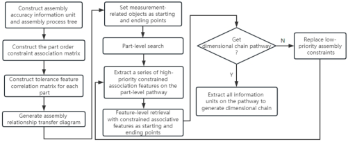
In this paper, the dimensional chain search process is divided into part- level and feature-level search, and the optimized Dijkstra algorithm is used to search the assembly relationship transfer diagram to obtain the shortest dimensional chain pathway (see Figure 1).
1) Part-level search. First of all, each part connected to the assembly con- straint unit of the assembly relationship transfer diagram is regarded as a
Figure 1: Dimensional chain generation process.
vertex, and the assembly constraint unit is regarded as an edge, the starting point and the end point are the measurement requirement unit UMR which is the part where the starting and ending elements of the closed loop are located, and the shortest part-level pathway is filtered out using the Dijkstra algorithm of heap optimization.
To consider the effect of assembly order, the assembly order value of the part assembled after the two parts related to the closed loop is counted as k. The constraints imposed by the part that is after the part in the assembly order can be eliminated during the retrieval process, and only the part consisting of the first k assembled parts(vertices) in the assembly relationship transfer dia- gram is searched, while for the case where parallel constraints(multiple edges) exist between the parts, refer to the rules preferring assembly constraints with high priority as dimensional chain paths, considering the assembly constraint priority and avoiding global search of the assembly relationship transfer dia- gram can significantly improve efficiency. Finally, the parts and assembly constraints that the path passes through are extracted to get the part-level dimensional chain path.
2)Feature-level search. The “Part--Assembly Constraint--Part...” path is generated for part-level searches. Each assembly constraint is created from two features of different parts through constraint relationships.
Then, using the tolerance-related features inside a single part as vertices and the tolerance cells as edges, extract the two features of the part that have assembly constraints with two adjacent parts as the starting and ending points of the search for the subsequent feature-level links, and use the heap- optimized Dijkstra algorithm to retrieve the assembly relationship transfer map to obtain the locally (within a single part)optimal feature-level pathway. All the feature-level pathways retrieved within the part-level pathway are combined to obtain the complete feature-level pathway.
By extracting all edges, i.e. dimensional tolerance units, geometric tolera- nce units and assembly constraint units, the complete assembly dimensional chain is obtained and can be used for the next dimensional chain calculation.
EXAMPLE ANALYSIS In this paper, based on the existing AMT system (Intelligent Assembly Pro- cess and Accuracy Prediction System) in the laboratory, we develop a set
Automatic Generation Technology 215
of dimensional chain calculation and analysis software for assembly accu- racy prediction based on the Qt5.13 application development framework, using Qt own Sqlite database as a data storage tool and the open source OpenCASCADE graphics library as a 3D processing module.
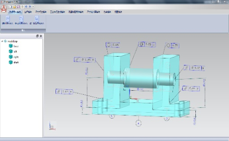
The following is an example of the stepped shaft assembly (see Figure 2). Assuming that the distance from the shaft to the base bottom surface is the assembly function requirement in the vertical direction, the automatic generation process of its assembly dimension chain is as follows: Step.1 Basic operations. Add assembly constraints to complete the deter- ministic positioning of the part, and select the base base surface and axis centerline as closed-loop elements to determine the measurement require- ments.
Step.2 Model analysis and pre-processing. The model is analyzed to obtain the information of assembly order, tolerance and assembly constraints to build a complete model of assembly accuracy information. In this exam- ple, there are 7 dimensional tolerance units, 7 geometric tolerance units, 10 assembly constraint units and 1 measurement requirement unit.
Step.3 Build the part order constraint correlation matrix. Combine the assembly order and assembly constraint unit information to build the part order constraint association matrix. In this example, the parts are assembled in the order of base, left bracket, shaft and right bracket. The constraints of base and bracket include face-to-face fit and face-to-face alignment, and the constraints of bracket and shaft include shaft hole interference fit and face-to-face fit. the sequential constraint association matrix is established as follows: [Equation or mathematical symbol available in the original paper PDF]
[Equation or mathematical symbol available in the original paper PDF] C(i, j) =
Equations and mathematical formulas are available in the original paper PDF.
φ {1, 2, 3} φ {8, 9, 10} {1, 2, 3} φ {4, 5} φ φ {4, 5} φ {6, 7} {8, 9, 10} φ {6, 7} φ Step.4 Establishing the tolerance feature association matrix. By analyzing the dimensional tolerance unit and geometric tolerance unit, the tolerance association features are obtained and the tolerance feature association matrix
Figure 2: Stepped shaft assembly.Figure 3: Assembly relationship transfer diagram and dimensional chain path.
is established. Taking the shaft as an example, the tolerance feature correla- tion matrix is established as follows: [Equation or mathematical symbol available in the original paper PDF][Equation or mathematical symbol available in the original paper PDF]
D(i, j) =
Equations and mathematical formulas are available in the original paper PDF.
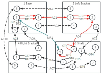
Step.6 Searching the assembly dimensional chain. Using the closed-loop feature element in the measurement information unit as the starting and ending points, as shown by the blue line (see Figure 3), we use the heap- optimized Dijkstra algorithm to perform part-level and feature-level searches of the assembly relationship transfer diagram to obtain the shortest assembly dimensional chain path. In this case, the later of the two parts to which the closed ring feature belongs is the shaft, and its assembly order is 3rd, there- fore, we only search the assembly relationship transfer diagram related to the part whose assembly order is before three. According to the assembly con- straint priority determination basis, the fit of the upper surface of the base to the lower surface of the bracket and the shaft hole fit of the bracket and the shaft are used in priority, and the part-level pathway obtained is “Base- -Assembly Constraint AC1--Left Bracket--Assembly constraint AC4--Shaft”, followed by feature-level searches for the base, left bracket and shaft respe- ctively, and the final assembly dimensional chain pathway obtained is shown as the red line (see Figure 3).
CONCLUSION
In this paper, we first abstract the key information used to automatically generate dimensional chains in the assembly model into various information units to more fully express the geometric and numerical relationships between
Automatic Generation Technology 217
various associated features in the model. Meanwhile, we focus on assem- bly characteristics such as assembly order and assembly parallel constraints, customize assembly constraint priorities, construct part order constraints and tolerance feature association matrices to generate assembly relationship tran- sfer diagrams, and use the sparsity of the transfer diagrams, use the shortest path algorithm of heap optimization, combine assembly order and constraint priorities to conduct local search on the transfer diagrams, which effectively improves the efficiency of automatic dimensional chain search, and at the same time makes the generated dimensional chains are more consistent with the actual assembly process planning.
REFERENCES
C. Y. Guo, J. H. Liu, et al. (2014). Automatic generation technology of assembly dimension chain based on graph theory, Computer Integrated Manufacturing Systems, vol. 20, pp. 2980–2990. H. Wang, R. Ning, and T. Yan. (2006). Simulated toleranced CAD geometrical
model and automatic generation of 3D dimension chains, International Journal of Advanced Manufacturing Technology, vol. 29, pp. 1019–1025. J. G. Li, Y. X. Yao, and P. Wang. (2014). Assembly accuracy prediction based on CAD model, International Journal of Advanced Manufacturing Technology, vol. 75, pp. 825–832. J. Q. Zhou, G. L. Chen, X. M. Lai, and Z. Q. Lin. (2005). Automatic Generation
of Dimension Chains for Auto-Body Dimensional Quality Evaluation, Journal of Compute-Aided Design and Graphics, vol. 17, pp. 1034–1038. M. F. Huang, Y. Y. Jiang, Z. Y. Liu, and G. Z. Ding. (2022). Research on Assembly Size Chain Ontology Method Considering Fit Deviation, Machinery Design and Manufacture, vol. 5, pp. 209–215. Q. W. Bao, Y. G. Fan, et al. (2016). A Method of Automatic Generation of Assem-
bly Dimension Chains Based on Information Cells, Journal of Computer-Aided Design and Computer Graphics, vol. 28, pp. 1989–1999. R. Z. Zhang, X. J. Liu, and Yi. Y. (2020). Technology of Automatic Generation and Update of Assembly Dimension Chain for Assembly Process, ICMA 2020, pp. 472–477. S. R, J. H. (1999). Tolerance Chain Detection by Geometrical Constraint Based
Coupling Analysis, Journal of Engineering Design, vol. 10, pp. 5–24. S. Y. Zheng, M. F. Huang, K. K. Zhang, et al. (2017). Automatic Generation of Dimension Chian Based on Assembly Constraints, Machine Design and Research, vol. 33, pp. 122–128. Z. B. Gao, J. W, Yanlong C, et al. (2016). Automatic Generation of 3D Assembly
Dimension Chain Based on Feature Model, Procedia CIRP, vol. 43, pp. 70–75. Z. B. Gao, Z. X. Wang, Z. J. Wu, and Y. L. Cao. (2015). Study on Generation of 3D Assembly Dimension Chain, Procedia CIRP, vol. 27, pp. 163–168. Z. Q. Zhang, J. H. Liu, X. Y. Ding, K. Jiang, and Q. W. Bao. (2017). Searching Multi-
branch Propagation Paths of Assembly Variation Based on Geometric Tolerances and Assembly Constraints, Journal of Mechanical Design, vol. 5, p. 139.
LISTED IN THE AHFE DIGITAL BOOKSTORE CATALOGUE
Explore the complete digital volume
Human Aspects of Advanced Manufacturing
Read this individual research paper free through the original publisher, or explore the full digital proceedings book.
ISBN 978-1-958651-56-8
Explore this ISBN in the AHFE Bookstore ↗Listed in the July 2026 bookstore catalogue; search by ISBN to confirm current availability · Digital book purchase optional