Jianqiang Liu, Xiaojun Liu (2025). Construction Method of Complex Product Repair Model for Process Execution End. In: Human Aspects of Advanced Manufacturing, Production Management and Process Control. AHFE Open Access, vol. 184, pp. 58–71. https://doi.org/10.54941/ahfe1006450
The performance of complex products is directly related to their assembly quality, and as a result, the precision requirements for assembling complex products are becoming increasingly stringent. However, in the assembly process, precision deviations are inevitable, often leading to situations where the required accuracy cannot be met. In such cases, rework and adjustment methods are needed to modify certain geometric attributes of the product model to ensure assembly precision. Currently, most rework solutions rely on the personal experience of on-site workers and repeated disassembly and reassembly, lacking scientific guidance. Aiming to improve the accuracy of rework solutions, this paper proposes a rework model construction method tailored for the process execution phase. First, an error propagation function is established based on the Small Displacement Torsor (SDT) and homogeneous transformation matrices. High-precision measurement equipment is then used on-site to collect point cloud data of key features, which is processed to reconstruct the error model of critical features, thereby enabling a more accurate error propagation model. Subsequently, an optimization-based dynamic adjustment mechanism and an interval resampling mechanism are introduced to improve the particle swarm optimization (PSO) algorithm. Using the improved PSO algorithm, more accurate rework plans are generated to guide on-site rework operations. Finally, a case study is conducted using the rework process of a satellite product subassembly structure to validate the proposed method. The results demonstrate that the proposed approach can generate more reasonable and effective rework solutions, not only improving on-site rework efficiency but also increasing the first-time assembly success rate of complex products.
The performance of complex products, such as satellites, aircraft, and machine tools, is directly influenced by their assembly quality (2024). Consequently, the precision requirements in the assembly process continue to increase. With the rapid advancement of machining technology, the quality of manufactured parts has significantly improved. However, the impact of error factors in the assembly process on assembly quality has also become increasingly significant (2018). Therefore, in the assembly process of complex products, it is essential to strictly control the assembly accuracy of critical nodes. This is especially true for single-piece and small-batch complex
Construction Method of Complex Product Repair Model for Process Execution End 59
products like satellites, where there is often no room for selecting alternative components. When the required assembly accuracy cannot be achieved, rework solutions must be provided to guide on-site rework operations.
First, assembly accuracy analysis is key to controlling product assembly quality and is a crucial factor in evaluating whether assembly quality meets the required standards. Liu et al. (2018) used the Small Displacement Torsor (SDT) to model key tolerances along the assembly path of helicopter rotor system components. They then applied the homogeneous coordinate transformation method for error propagation analysis, ultimately obtaining the geometric rotational accuracy of the rotor system. Hu et al. (2024) employed SDT and skin model shapes to construct a comprehensive tolerance model for precision spindles. Zeng et al. (2024) built a coupling model of assembly deviation and static mechanics to analyze the relationship between assembly deviation and the mechanical characteristics of the bearing system. Yi et al. (2024) proposed a digital twin-based assembly accuracy prediction method for complex aerospace product assembly, utilizing virtual-physical integration for assembly process modeling and analysis to enhance assembly quality and performance stability.
On assembly sites, rework methods are typically used to adjust product assembly accuracy, making feasible rework solutions necessary for guidance. Sun (2022) addressed the weak correlation of stable knowledge in assembly processes by proposing a knowledge graph-based representation method for assembly processes. This method leverages the inferential capabilities of knowledge graphs to dynamically adjust assembly processes. Guo et al. (2023) established three single-objective optimization models for machining cost, quality loss, and rework cost. They then constructed a multi-objective tolerance optimization allocation model based on a weight parameter distribution method for multi-objective models, solving it using an accelerated particle swarm optimization algorithm to determine the error values for each component loop. Chen et al. (2022) tackled the issue of unpredictable rework volume for large aerospace structural components. They employed fuzzy comprehensive evaluation to quantify factors such as rework cost and difficulty, thereby recommending rework solutions.
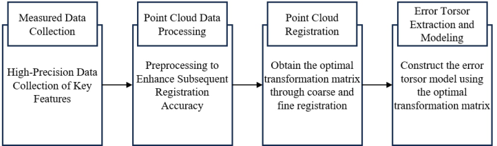
Error Propagation Model Construction Method Based on Twin Data In the field of assembly error modeling, the Small Displacement Torsor (SDT) model is commonly used to describe the tolerance variations of typical component features (2018). Additionally, homogeneous transformation matrices from rigid body kinematics in robotics are utilized to construct error propagation models (2023). The error propagation model of complex products serves as the foundation for generating rework solutions. Traditional error propagation models rely on the analysis and calculation based on the design data of complex products, which cannot promptly reflect the actual geometric variations of products in the assembly environment. Therefore, it is necessary to collect point cloud data using high-precision measurement equipment at the assembly site after completing critical assembly steps. This enables the reverse reconstruction of key features. The specific implementation steps are shown in Figure 1.
60 Liu and Liu
Figure 1: The process of key feature reconstruction.
After completing the actual assembly of critical assembly steps, high- precision measurement equipment at the assembly site is used to obtain the measured geometric feature data. Once the raw point cloud data is collected, preprocessing techniques such as denoising, hole filling, and data downsampling are applied to improve the accuracy of subsequent point cloud registration and enhance analytical efficiency.
Point cloud registration is the core step for aligning the measured data with the design model. Its objective is to eliminate pose deviations between the two through geometric transformations, enabling the precise extraction of assembly errors. Based on the preprocessed point cloud, the reconstruction of key assembly features is achieved through three main steps: coarse registration, fine registration, and error torsor extraction.
Coarse registration aims to rapidly estimate the initial transformation matrix between the measured point cloud and the design model by extracting prominent geometric features, thereby providing a good initial pose for subsequent fine registration. Its core process includes feature description, correspondence matching, and transformation matrix computation.
First, the Fast Point Feature Histogram (FPFH) descriptor is used to characterize the local geometric features of the point cloud. FPFH is highly robust to noise and variations in point cloud density, making it suitable for representing complex geometric features. By statistically analyzing the geometric property distribution within a point’s neighborhood, FPFH generates a highly discriminative 33-dimensional feature vector. For a given point pi, the computation of its FPFH features consists of three main steps: neighborhood construction, geometric property calculation, and histogram statistics.
Step 1: Neighborhood Construction Centering on point pi, a spherical neighborhood with a radius of r = 5mm is constructed, containing neighboring k = 50 points.
Step 2: Geometric Property Calculation Step 2.1: Calculation of the Normal Vector Angle The angle between the normal vectors of point pair
is computed as:
Equations and mathematical formulas are available in the original paper PDF.
where −→ ni and −→ nj are the normal vectors of points pi and pj, respectively.
Construction Method of Complex Product Repair Model for Process Execution End 61
Step 2.2: Calculation of Local Curvature The local curvature is computed as: ∅= λ1/(λ1 + λ2 + λ3)
where λ1 ≤λ2 ≤λ3 are the eigenvalues of the covariance matrix of the neighborhood.
Step 3: Histogram Statistics The parameters α and ∅are discretized into a 33-dimensional histogram, generating the feature vector fi∈R33.
Next, the Random Sample Consensus (RANSAC) algorithm is applied to filter out the optimal correspondence point set and estimate the initial transformation matrix H0H_0. RANSAC enhances iterative random sampling and model verification by randomly selecting three non-collinear point pairs from the matched point set to construct a minimal sample set and compute the rigid transformation matrix. The specific process is as follows: Step 1: Random Sampling Randomly select three non-collinear point pairs from the matched point set to form a minimal sample set (Minimal Set).
Step 2: Model Hypothesis Based on the minimal sample set, compute the candidate rigid transformation matrix Hcandidate, which includes the rotation matrix R and the translation vector −→t .
Step 3: Inlier Selection Set a distance threshold dmax = 0.1mm and count the number of inliers that satisfy:
i −Hcandidate · pdesign i
pmeas
Step 4: Iterative Optimization Repeat the above process N = 1000 times, and select the transformation matrix Hcandidate with the highest inlier ratio as the initial transformation matrix H0. The mathematical expression is:
Internal points
The physical significance of the initial transformation matrix H0 is to map the design model from the ideal coordinate system to the measured coordinate system. Its mathematical form is given by:
R0 t0
In the equation, R0 ∈SO (3) represents the rotation matrix, and t0 ∈ R3 represents the translation vector. After coarse registration, the average alignment error between the measured point cloud and the design model is typically reduced to within 1 mm.
62 Liu and Liu
The accuracy of coarse registration is insufficient to support the precision prediction of high-precision complex products. Therefore, fine registration is required to achieve higher accuracy in point cloud alignment. Fine registration is performed using the Iterative Closest Point (ICP) algorithm, which further optimizes the transformation matrix and enables sub- millimeter-level point cloud alignment. The ICP algorithm is one of the most widely used fine registration methods in point cloud processing. Its objective is to iteratively optimize the alignment by minimizing the distance error between corresponding points in the two point clouds, ultimately achieving high-precision alignment.
First, a three-dimensional KD-tree (K-Dimensional Tree) data structure is constructed for the design model point cloud Pdesign, reducing the time complexity of nearest neighbor search from O
N2
to O
N log N
. A bidirectional consistency check is then performed to ensure the accuracy of the corresponding point pairs.Next, the Singular Value Decomposition (SVD) method is used to solve for the optimal transformation matrix. For the k-th iteration, given N pairs of corresponding points, the optimal transformation matrix is obtained by minimizing the objective function. After decentralizing the coordinates, the covariance matrix is computed and decomposed using SVD to derive the optimal rotation matrix and translation vector. The specific steps are as follows: Step 1: Nearest Point Search Utilizing a KD-tree for accelerated searching, each point psource i in the source point cloud is matched with its nearest corresponding point ptarget
i in the target point cloud based on geometric distance.
Step 2: Transformation Matrix Estimation Based on the corresponding point pairs, the optimal rigid transformation T = (R, t) is solved using the least squares method. The specific steps are as follows: Step 2.1: Compute the Centroids of the Source and Target Point Clouds
N X
psource
ptarget
Step 2.2: Covariance Matrix Construction T N X
psource
ptarget
i −µsource
i −µtarget
VT (6)
Construction Method of Complex Product Repair Model for Process Execution End 63
t = µtarget −Rµsource (8) Step 3: Convergence Criteria and Termination The ICP algorithm iteratively adjusts the transformation matrix until the registration error is minimized or the predefined maximum number of iterations is reached. A common convergence criterion is that the change in registration error falls below a certain threshold. Specifically, the iteration terminates when the change in Root Mean Square Error (RMSE) between two consecutive iterations is smaller than the threshold. The residual error at the k-th iteration is denoted as ε(k):
N X
2 (9)
j
i + t(k) −ptarget
v u u t 1 N
Additionally, a maximum iteration count kmax can be set to prevent the algorithm from getting stuck in an infinite loop.
By following the above steps, the ICP algorithm continuously optimizes registration accuracy until it converges to the optimal solution, thereby achieving precise alignment between point clouds.
After fine registration, the transformation matrix needs to be decomposed into rotation and translation components to construct a SDT model for quantifying assembly errors. The rotation matrix can be converted into a rotation vector using the matrix logarithm mapping. The rotation vector and translation vector are then combined into an error torsor, which intuitively represents deviations in six degrees of freedom (three translations and three rotations), providing a mathematical basis for subsequent tolerance analysis.
Following the above process, the optimal transformation matrix Hmeas obtained from point cloud registration using the ICP algorithm is:
Rmeas tmeas 0T 1
Rotation vector extraction: The rotation matrix is converted into a rotation vector θmeas using the matrix logarithm mapping: θmeas = log (Rmeas) (11)
(12)⃗
[Equation or mathematical symbol available in the original paper PDF]
R32 −R23 R13 −R31 R21 −R12
64 Liu and Liu
Translation Vector Extraction: The translation component is directly obtained as tmeas.
Summary, The error torsor model Terror is given by:
θmeas tmeas
By applying the above methods, the reverse reconstruction of key features can be achieved, allowing the correction of the model using measured data. This process helps in constructing a more accurate error propagation model, thereby laying a stronger foundation for the generation of subsequent rework solutions.
A Rework Solution Generation Method Based on an Improved Particle Swarm Optimization Algorithm In the assembly process of complex products, when the assembly accuracy does not meet the inspection requirements, it is necessary to rework certain structural features of components. However, the current rework approach primarily relies on the experience of on-site workers, using repeated trial assembly, measurement, and adjustment methods. Since the rework range is often estimated roughly, the entire process involves significant uncertainty, making it difficult to ensure rework quality while balancing cost control and operational efficiency.
Since its introduction, the particle swarm optimization (PSO) algorithm has been widely applied in various fields and has become an essential tool for solving complex optimization problems. With further research, many improved PSO algorithms (such as hybrid PSO and modified PSO) have been proposed, expanding its adaptability and optimization effectiveness in practical applications.
In the field of assembly, the application of PSO for generating rework solutions still faces the following challenges:
1. In the assembly process, there are usually multiple constraints, such as assembly sequence, spatial limitations, and types of geometric tolerances. Since these constraints are often nonlinear and non-convex, the solution space is typically highly complex and contains multiple local extrema, making it easy for PSO to fall into a local optimal solution, resulting in poor optimization results. 2. The optimization results of the PSO algorithm are specific numerical values rather than feasible rework intervals, which does not meet the practical requirements of rework.
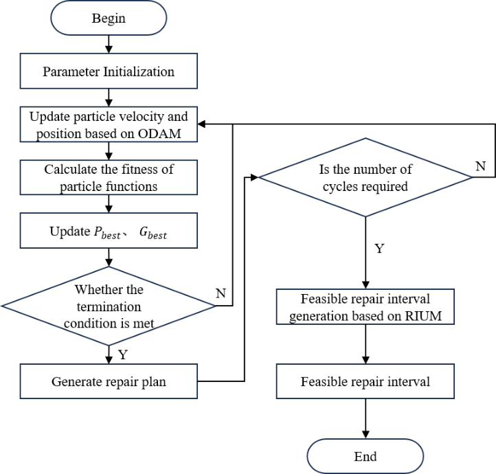
Therefore, to better apply the method for generating rework solutions, this paper proposes a rework solution generation strategy based on an improved particle swarm optimization (IPSO) algorithm, as shown in Figure 2, which mainly adds the following mechanisms:
1. Optimization Dynamic Adjustment Mechanism (ODAM): This introduces random weights and asynchronous learning factors, allowing
Construction Method of Complex Product Repair Model for Process Execution End 65
the particles’ velocities to be dynamically adjusted during iterations, thus avoiding the algorithm from falling into local optimal solutions. 2. Repair Interval Upsampling Mechanism (RIUM): In this paper, the optimization targets for IPSO particles are the geometric tolerances along the error propagation path. Based on the characteristics of the error propagation model, the relationship between geometric tolerances and assembly accuracy of the target features is linear. Therefore, the repair interval upsampling mechanism is introduced to record feasible solutions that meet inspection requirements, generating multiple sets of feasible rework solutions. The upsampling method, inspired by signal processing, forms the repair interval upsampling mechanism to create feasible rework intervals.
(1) Optimization Dynamic Adjustment Mechanism Therefore, this paper introduces random weights and asynchronous learning factors to enhance the optimization capability of the algorithm. The iterative update equations for the velocity and position in the improved particle swarm optimization (IPSO) algorithm are given as follows:
pbest
gbest
+ c2 · r2
i −xi(t)
Where: vi (t) represents the velocity of the i-th particle at iteration t, xi (t) represents the position of the i-th particle at iteration t, ω is the random relationship weight, c1 and c2 are asynchronous learning factors, r1 and r2 are random factors, typically generated within the range [0,1], pbest
i is the historical best position of particle i, gbest
i is the global best position. The random weight is defined as: ω = µmin + rand() × (µmax −µmin) + σ × randn() (18)
where: µmin and µmax are the minimum and maximum values of the random inertia weight, respectively, rand() is a uniformly distributed random number in the range [0, 1], randn()is a normally distributed random number with a mean of 0 and a standard deviation of 1, σ is the standard deviation, which controls the magnitude of the random fluctuation.
The asynchronous learning factors are defined as: c1 = (c1e −c1s) (t −tmax)/tmax + c1e (19)
c2 = (c2e −c2s) (tmax −t)/tmax + c2e (20) where: c1s and c2s are the starting values of the learning factors c1 and c2,with c1s = c2s = 2.5, c1e and c2e are the ending values of the learning factors c1 and c2, ensuring that c1 and c2 change asynchronously.
66 Liu and Liu
(2) Repair Interval Upsampling Mechanism (RIUM) To enhance the exploration capability of feasible solution spaces for geometric tolerances in complex assembly systems, this paper proposes a repair interval upsampling mechanism (RIUM). The core idea is to integrate the particle swarm optimization algorithm with the upsampling concept from the signal processing domain, expanding the feasible solution set through interpolation and generating multiple rework intervals.
First, during the iterative process of the improved PSO algorithm, feasible solutions that satisfy the constraint conditions in each dimension are recorded to construct an initial feasible solution set F = {x1, x2, · · · xn}, where xi represents a feasible solution in a specific dimension, and N is the total number of feasible solutions.
Based on this set, considering that the distribution of feasible solutions in the solution space exhibits non-uniform characteristics, a Gaussian Process Interpolation (GPI) method is adopted to balance local precision and global adaptability.
Subsequently, the feasible solution set undergoes interpolation to generate candidate solutions. Specifically, for two adjacent feasible solutions xi and xj, an intermediate solution xij is generated using an interpolation coefficient (0 < α < 1). The expression is given by:
xj −xi
By repeating this operation, an upsampled candidate solution set Fupsampled is formed. Candidate solutions that do not meet the constraint conditions are then eliminated to ensure the feasibility of the solutions.
Furthermore, statistical analysis is conducted to determine the range of the rework interval. The mean µ and standard deviation σ of the candidate solution set are calculated as follows:
M X
2 (23)
xk −µ
where M is the number of candidate solutions. Based on this, the rework interval can be defined as: Tinterval = [µ −k · σ, µ + k · σ] (24)
In the equation, the expansion coefficient kk is used to adjust the interval width. Finally, the repair interval Tinterval is divided into multiple sub- intervals, with each sub-interval corresponding to a set of feasible rework solutions. This process forms a high-density feasible region within the solution space.This mechanism dynamically expands the solution space, effectively enhancing the diversity and robustness of rework solutions. It provides a more comprehensive optimization foundation for complex assembly scenarios.
Construction Method of Complex Product Repair Model for Process Execution End 67
When the assembly accuracy of critical assembly steps in the complex product assembly process does not meet the required standards, the improved particle swarm optimization algorithm can enhance the efficiency of particle optimization and prevent it from getting trapped in local optima. This enables the generation of more efficient and precise rework solutions.The dimensions of the particle swarm represent the number of rework regions, and particles perform optimization iterations within the solution space. Each particle corresponds to a generated rework solution. After each iteration, the results are substituted into the assembly accuracy analysis model to obtain the corresponding assembly accuracy, which serves as the function fitness.The rework solution generation method based on IPSO, as shown in Figure 2, yields feasible rework solutions.
Figure 2: Method for generating repair plans based on IPSO.
CASE STUDY To validate the effectiveness of the proposed rework solution generation method for the process execution phase, a case study is conducted using the assembly process of a satellite product subassembly structure. This
68 Liu and Liu
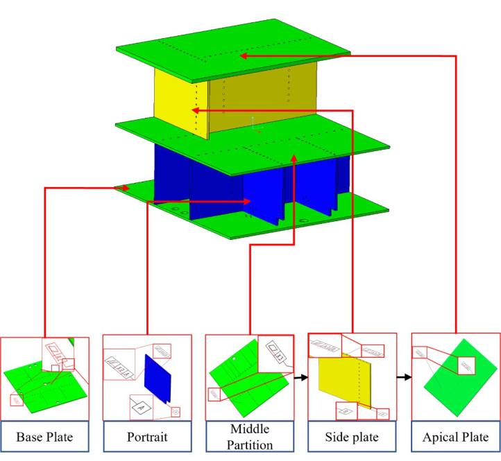
subassembly structure consists of multiple assembly steps, including the base plate, vertical plates, intermediate partitions, side panels, and top plate, involving 15 error terms in the error propagation paths.
By performing reverse reconstruction of key features and generating rework solutions, the accuracy of the proposed method is verified.
Figure 3: Transmission path of structural errors in a certain satellite component.Table 1: Structural error term and number of a certain satellite.
Table available in the original PDF paper.
Geometric Features Error Term Error Number Surface on the base plate δZ1 (X) , εX1(X), εY1(X) 1, 2, 3 Surface on the portrait δZ2 (X) , εX2(X), εY2(X) 4, 5, 6 Surface on the middle partition δZ3 (X) , εX3(X), εY3(X) 7, 8, 9 Surface on the side plate δZ4 (X) , εX4(X), εY4(X) 10, 11, 12 Surface on the apical plate δZ5 (X) , εX5(X), εY5(X) 13, 14, 15
Taking the satellite product subassembly structure shown in Figure 3 as an example, high-precision measurement equipment (laser tracker) is used to collect actual assembly data. The error term values range from ±50 µm (positional error) to ±0.001 rad (angular error).
Construction Method of Complex Product Repair Model for Process Execution End 69
Using the base plate mounting surface as a case study, its geometric features are reconstructed from high-precision point cloud data, and the error torsor model is extracted. A 3D scan of the base plate mounting surface is performed, capturing approximately 60,000 raw point cloud data points with a point spacing of 0.1 mm and a scanning accuracy of ±0.02 mm.
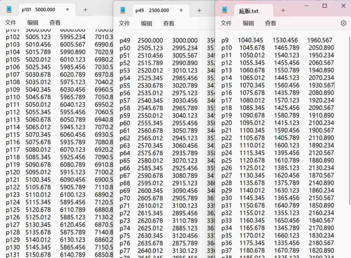
The point cloud data is then preprocessed, reducing the number of points to 40,000, achieving a retention rate of approximately 67%. A subset of the measured point coordinate data is shown in Figure 4.
Figure 4: Actual measurement data of the base plate installation surface (partial).
Based on the RANSAC algorithm, three sets of non-collinear points are randomly sampled. The inlier threshold is set as dmax = 0.1mm. After 1000 iterations, the initial transformation matrix H0 is obtained:
[Equation or mathematical symbol available in the original paper PDF]
[Equation or mathematical symbol available in the original paper PDF]
Equations and mathematical formulas are available in the original paper PDF.
0.9998 0.0053 −0.0172 0.12 −0.0051 0.9999 0.0086 −0.09 0.0173 −0.0085 0.9998 0.05 0 0 0 1 Then, based on the ICP algorithm, fine registration is performed. After 15 iterations, the final transformation matrix Hmeas is obtained:
[Equation or mathematical symbol available in the original paper PDF]
[Equation or mathematical symbol available in the original paper PDF]
Equations and mathematical formulas are available in the original paper PDF.
Based on the final transformation matrix Hmeas, the error torsor is extracted. Using equations (11) to (14), the calculated rotation angle is: θX = arcsin (R32) = arcsin(−0.001) ≈−0.001rad (27)
tZ = −0.05 mm (29) Therefore, the error torsor model Terror for the reconstructed base plate mounting surface feature based on point cloud data is given by:
[Equation or mathematical symbol available in the original paper PDF]
[Equation or mathematical symbol available in the original paper PDF]
[Equation or mathematical symbol available in the original paper PDF]
Using Creo software, a sensitivity analysis of the model is conducted, revealing that the upper surface of the intermediate partition has high sensitivity. Therefore, rework simulation is performed specifically for this surface.
The particle swarm is configured with a population size of 50 and a maximum of 200 iterations. The learning factor c1 decreases linearly from 2.5 to 1.0, while c2 increases from 1.0 to 2.5. The inertia weight ω is set within the range [0.4, 0.9].
During the particle swarm iteration process, feasible solutions satisfying the constraints are recorded as F = {−0.07, −0.08, −0.09}. Using equation (21) for interpolation between adjacent solutions with α = 0.05, intermediate solutions are generated as x12 = −0.075, x23 = −0.085, expanding the candidate solution set to {−0.07, −0.075, −0.08, −0.085, −0.09}. Substituting these values into the error propagation function confirms that they all meet the accuracy requirements.
Then, using equations (22) and (23), the mean is calculated as µ = −0.08 and the standard deviation as σ = 0.007. Applying equation (24), the feasible rework interval is: Tinterval = [µ −1.5σ, µ + 1.5σ] = [−0.0905, −0.0695]
In conclusion, when the top plate assembly accuracy does not meet the requirements, the interference error in the Z direction can be eliminated by filing the embedded parts on the contact surface between the intermediate partition and the vertical plate. The feasible rework range is [−0.0905, −0.0695] mm.
Implementing the rework process based on the proposed method significantly improves the feasibility and efficiency of the rework solution, providing scientific guidance for the rework of complex products.
Construction Method of Complex Product Repair Model for Process Execution End 71
CONCLUSION
This paper addresses the issue of generating rework schemes in the complex product assembly process and proposes a rework model construction method oriented toward the process execution end. High-precision measurement equipment is used to obtain point cloud data of target features, enabling reverse reconstruction of these features based on the point cloud data. This approach facilitates the construction of a more accurate error propagation model. Additionally, an Optimization Dynamic Adjustment Mechanism (ODAM) and a Repair Interval Upsampling Mechanism (RIUM) are introduced to enhance the particle swarm optimization (PSO) algorithm. Based on the improved PSO algorithm, feasible rework intervals are generated. Case studies validate that this method effectively improves the first-pass assembly success rate and rework efficiency for complex products.
Future research can further optimize the algorithm for generating rework schemes by incorporating additional practical assembly constraints and verifying the model with more real-world cases to enhance its accuracy and applicability. Furthermore, with the continuous advancement of digital twin technology, the real-time performance and intelligence level of the rework model will be further improved, providing more reliable assurance for the assembly quality of complex products.
REFERENCES
Chen S, Bai T, Zhang Y, Fang Z, Chen Z. Geometric error suppression of six-axis machine tool for blisk full-shape surface grinding via constrained error sensitivity analysis. Precis Engineering, 2024;88: 1–14. Chen Shuai, Guo Feiyan, Meng Yuemei, et al. Iterative Optimization and Evaluation
Method for Repair Quantity of Aviation Structural Parts Considering Measured Data[J]. China Mechanical Engineering, 2022, 33(17):2061-2070+2078. Guo Feiyan, Song Changjie, Zhang Shuo, et al. Multi-objective model fusion method for tolerance allocation orienting to accuracy and process improvement[J]. Computer Integrated Manufacturing Systems, 2023, 1–28. Hu Xiaokun, Yang Yitao, Zhao Qiangqiang, et al. Rotation accuracy analysis
for precision spindles based on skin model[J]. Aeronautical Manufacturing Technology, 2024, 67(16): 74–84. J. W. Cheng, W. J. Bu, L. Shi, et al., A real-time shaft alignment monitoring method adapting to ship hull deformation for marine propulsion system, ech. Syst. Signal Process.197(2023)110366. Khan, H. A.; Butt, S. U.; Baqai, A. A.; Saeed, H. A. A new approach to predict the
flexibility and precision of manufacturing systems using geometric constraints and small displacement torsors. Procedia Manuf. 2018, 17, 294–301. Liu Jianhua, Sun Qingchao, Cheng Hui, et al. The State-of-the art, connotation and developing trends of the products assembly technology[J]. Journal of Mechanical Engineering, 2018, 54(11): 2–28. Sun Xuemin. Theoretical Research and Application of High Precision Products
Assembly-Commissioning Driven by Digital Twin[D]. Shanghai: Donghua University, 2022. Yi Y., Zhang A. Q., Liu X. J., et al. Digital twin-driven assembly accuracy prediction method for high performance precision assembly of complex products[J]. Advanced Engineering Informatics, 2024, 61:102495. Zeng W. H., Lu W. L., Xun F. Model-based low-speed rotation error prediction for
the rigid shaft-bearing system considering the assembly deviation[J]. Mechanism and Machine Theory, 2023, 184:105294.
LISTED IN THE AHFE DIGITAL BOOKSTORE CATALOGUE
Explore the complete digital volume
Human Aspects of Advanced Manufacturing, Production Management and Process Control
Read this individual research paper free through the original publisher, or explore the full digital proceedings book.
ISBN 978-1-964867-60-1
Explore this ISBN in the AHFE Bookstore ↗Listed in the July 2026 bookstore catalogue; search by ISBN to confirm current availability · Digital book purchase optional