Bobby Mathew, Fadi Alnaimat (2024). Use of computational fluid dynamics in the design and analysis of heat exchange devices. In: Human Factors in Design, Engineering, and Computing. AHFE Open Access, vol. 159, pp. 227–233. https://doi.org/10.54941/ahfe1005586
A high-performance heat exchanging devices are gaining traction in many applications. This study aims to investigate heat transfer in a microchannel heat exchanger. A computational fluid dynamics (CFD) model is developed to examine performance under various flow conditions, assuming a steady-state operating condition. The effectiveness of the heat exchanger is studied by varying the inlet flow rate, with investigations conducted for different Reynolds numbers ranging from 200 to 2000. A single channel repeating unit from both the hot and cold sides of the heat exchanger is modeled. The effectiveness of the heat exchanger is determined using the inlet and outlet thermal condition of the heat transfer fluids. The thermal performance of the heat exchanger, including effectiveness and overall heat transfer coefficient, is examined for different flow rates. The effectiveness of the heat exchanger strongly depends on the channel size. It is found that increasing the Reynolds number decreases effectiveness while increasing the overall heat transfer coefficient. It is concluded that the use of microchannel can significantly improve the performance of heat exchangers in many applications. Using CFD can be substantial enhance understanding of fluid and heat transfer in heat exchanging devices.
In many different industries, including aerospace, microelectronics, robotics, biomedical, automotive, nuclear, power plants, and chemical processing, two-fluid heat exchangers are widely used for a variety of purposes, such as air conditioning, heating, and cooling, as well as chemical processing and the cooling of electronic chips. Enabling heat transfer between two fluids at different temperatures is the primary purpose of a two-fluid heat exchanger. The second law of thermodynamics states that heat transfers from one body at a high temperature to another at a low temperature when two bodies are at different temperatures (Cengal, 2010).
Hot and cold fluids, respectively, enter the heat exchanger at high and low temperatures. In addition, a solid wall keeps the two fluids in the two-fluid heat exchanger apart to prevent them from mixing. Convection
transfers heat between the fluids and the wall, dividing them, and conduction transfers heat within the wall (Sekulic et al., 2003), (Kakac et al., 2012), (Mathew et al., 2015). Two-phase heat exchangers are those in which the working fluid undergoes a phase change while absorbing or rejecting heat. However, heat exchangers in which the working fluids do not undergo phase change as a result of heat addition or rejection are referred to as single-phase heat exchangers. Different types of heat exchangers have been produced as a result of the diverse uses for heat exchangers. A straightforward heat exchanger design comprises two concentric cylinders, one for a hot or cold fluid that fills the inner cylinder’s volume and another for a cold or hot fluid that fills the space between the cylinders. This type of heat exchanger is known as a double pipe heat exchanger. Compact heat exchangers and shell and tube heat exchangers are two other well-known varieties of heat exchangers based on construction.
Researchers have been looking into different methods for increasing heat transfer coefficient in addition to using small channels in heat exchangers. Techniques for reducing channel dimensions and increasing the heat transfer coefficient fall into two categories: passive and active. Techniques classified as passive do not need any outside power, whereas techniques classified as active do. In order to increase the heat transfer coefficient, both passive and active methods thin the boundary layer and create secondary flow (Alkhazaleh et al., 2023), (Alnaimat, 2022), (Alkhazaleh et al., 2023), (Alnaimat, 2023). Model-based studies of a MEMS parallel flow two-fluid heat exchanger operating in laminar flow conditions were conducted (Alnaimat et al., 2021). Pin fins embedded in straight microchannels were used in the MEMS heat exchanger. Research is conducted on Reynolds numbers between 50 and 2000 as well as heat capacity ratios between 0.5 and unity. They found that the effectiveness was increased with pin fins for a given Reynolds number, and that this improvement was correlated with a rise in pumping power. An experimental testing was carried out to investigate heat transfer in pin-fin heat sinks for cooling applications (Alnaimat et al., 2022). A range of pin-fin sizes and operating parameters, such as heat flux and Reynolds numbers, were tested experimentally. It was discovered that, in comparison to fin size, fluid velocity had a more noticeable impact on thermal resistance. An experimental and numerical investigation of air-mist cooling in minichannel heat sinks was conducted (Alnaimat et al., 2022). The application of air- mist based cooling resulted in a notable improvement in heat transfer performance.
A shell-and-tube heat exchanger is made up of several small pipes arranged inside of a large cylinder; the fluids within the small pipes are either hot or cold, while the fluids outside the pipe are either cold or hot. Compact heat exchangers are the third most common type of heat exchangers in terms of construction. They are made up of several layers, each of which is devoted to a different fluid (hot or cold) and has multiple flow passages. Additionally, a solid wall divides each flow passage from the others in both the same layer and adjacent layers. Compact heat exchangers have the highest compactness, or surface area to volume ratio, usually greater than 300 m2/m3 (Sekulic et al., 2003) (Kew et al., 2011), (Reay et al., 2013), (Singh et al.,
Use of Computational Fluid Dynamics in the Design and Analysis 229
2019). Therefore, compact heat exchangers are any heat exchangers that use channels that have a hydraulic diameter of less than 10 mm (Sekulic et al., 2003), (Kew et al., 2011), (Reay et al., 2013), (Singh et al., 2019). Heat exchangers can also be categorized according to how the fluid flows; these include cross, parallel, and counterflows. This work would cover the two flow arrangements of parallel and counter flows. The hot and cold fluids enter the heat exchanger at the same point and flow in parallel to exit at the opposite end, which is known as the parallel flow arrangement. In contrast, hot and cold fluids enter the heat exchanger at different ends, flow in the opposite direction, and exit at different ends when there is a counterflow arrangement.
The analysis of the two-fluid heat exchanger with staggered pin-fin arrangement in the channels is the goal of this work. The heat and mass transfer inside the heat exchanger are described by mathematical modeling. As part of this study, a parametric analysis of the conceptualized heat exchanger is conducted to determine how operating conditions affect the heat exchanger’s hydraulic and thermal performance.
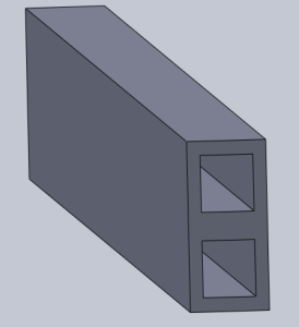
MATHEMATICAL MODELING The minichannel heat exchanger consists of several minichannels in each layer for the hot and cold fluids. There are 2 layers of channels for the hot and cold fluids to flow. The CAD model of a single channel heat exchanger is shown in Figure 1. The depth and width of a single channel is 2 mm. Water is used as the working fluid. The hot water enters the channel at 80 oC and the cold water enters at 20 oC.
Figure 1: CAD model of the channel heat exchanger.
A single repeating channel from the hot and cold fluid of the heat exchanger is modeled. The heat exchanger effectiveness is an important parameter and need to be determined. The effectiveness is defined as:
Tc,o −Tc,i
Th,i −Th,o
= Ch
ε =
= Cc
(1)
Cmin
Cmin
Th,i −Tc,i
Th,i −Tc,i
˙Q ˙Qmax
230 Mathew and Alnaimat
where T (K) represents the fluid temperature, C (J/K) is the fluid heat capacity C = ˙mcp, i represents the inlet, o represents outlet, h represents the hot fluid, c represents the cold fluid, and min represents the minimum. The heat capacity ratio is defined as Cr = Ch Cmin = Cc Cmin . It is to be noted that the effectiveness is dependent on several geometrical and operational parameters including ε = f
Dhy,ch, U, Lch, Vh, Vc, ρh, ρc, cph, cpc
. The heat transfer rate is determined as, ˙Q = UA1Tlm,CF (W) (2)
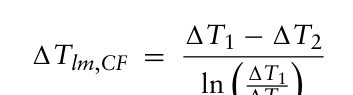
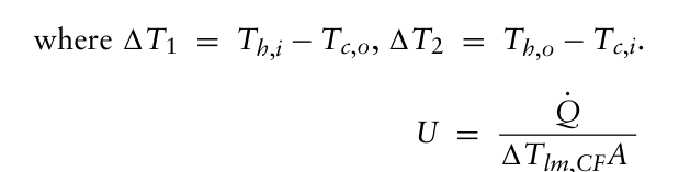
where U is overall heat transfer coefficient, A is the heat transfer area, Tlm,CF is the logarithmic mean temperature difference which is defined as,
Equation reproduced from the original PDF.
(3)
ln 1T1 1T2
Equation reproduced from the original PDF.
˙Q 1Tlm,CFA (4) It is to be noted that the overall heat transfer coefficient for the heat exchanger can be obtained as,
1
1
1
=
+
+
(5)
kS
1 UAs
hAs
hAs
h w
c where h (W/m2K) is the heat transfer coefficient associated with the fluid, k (W/mK) is the thermal conductivity.
RESULTS AND DISCUSSION
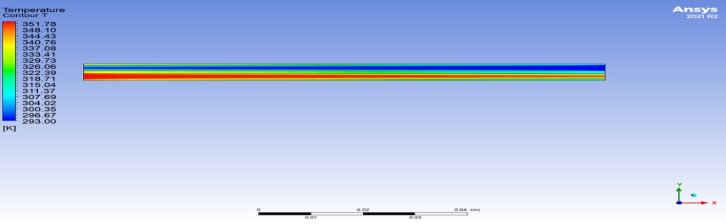
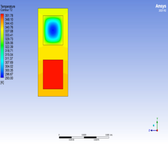
Figure 2 shows the temperature distribution in the minichannel heat exchanger. It is shown in Figure 2 that the temperature of the hot fluid decreases in the flow direction and the temperature of the cold fluid increases in the flow direction. Figure 2 shows the temperature distribution in the minichannel. It is also shown that the temperature changes in a channel along the flow direction. It is noticed that the temperature near the wall changes more rapidly compared to that away from the surface. This is due to the proximity of the surface were the fluid temperature reaches near the surface temperature. The hot fluid enters the minichannel at a temperature of 353 K and exits at lower temperature around 340 K. The cold fluid enters the minichannel at a temperature of 293 K and exits at higher temperature around 304 K. Figure 3 shows the temperature distribution in the minichannel heat exchanger at the inlet and outlets of both hot and cold fluids. As noticed in Figure 3, the hot fluid temperature at the inlet is uniform as specified by the CFD software, and non-uniform at the outlet where the maximum in the center. This to due to heat transfer to the cold fluids.
Use of Computational Fluid Dynamics in the Design and Analysis 231
Figure 2: Temperature distribution in the minichannel heat exchanger (Th,in= 80 oC, Tc,o =20 oC, Reh = 600, Cr = 1).Figure 3: Temperature distribution at the inlet and outlet of the minichannel heat exchanger (Th,in= 80 oC, Tc,o =20 oC, Reh = 600, Cr = 1).
Similarly, the cold fluid temperature at the inlet is uniform, and non-uniform at the outlet where the minimum in the center.
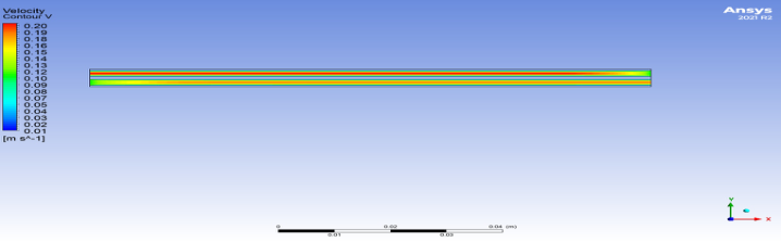
Figure 4 shows the velocity distribution in the minichannel heat exchanger. It is noticed that the maximum velocity is in the center of the channel. Similarly, the cold fluid and hot fluid velocity at the inlet is uniform, and non-uniform at the outlet where the maximum in the center. This is due the low friction at the center, and higher friction near the channel surface.
Figure 4: Velocity distribution in the minichannel heat exchanger with side (Th,in= 80 oC, Tc,o =20 oC, Reh = 600, Cr = 1).
232 Mathew and Alnaimat
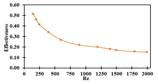
Figure 5 shows the effectiveness for different Reynolds number for a minichannel heat exchanger. It is observed that the effectiveness decreases with increasing Reynolds number. This is due to the increase in mass flow rate with increasing Reynolds number which leads to increasing the maximum heat transfer in the heat exchanger ˙Qmax.
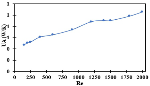
Figure 6 shows the overall heat transfer coefficient for different Reynolds number for minichannel heat exchanger. It is shown that the heat transfer coefficient increases with increasing Reynolds number. This is attributed to the increase in fluid velocity with increase in mass flow rate which leads to increase the heat transfer in the minichannel.
Figure 5: Effectiveness of the minichannel heat exchanger for different Reynolds number (Th,in= 80 oC, Tc,o =20 oC, Reh = 600, Cr = 1).Figure 6: Overall Heat transfer coefficient of the minichannel heat exchanger for different Reynolds number (Th,in= 80 oC, Tc,o =20 oC, Reh = 600, Cr = 1).
CONCLUSION
Investigations are conducted into the heat exchanger’s performance under various operating circumstances. A computational simulation model is created to investigate the efficiency and rate of heat transfer. The study is
Use of Computational Fluid Dynamics in the Design and Analysis 233
conducted for various Reynolds numbers ranging from 200 to 2000. The fluids’ inlet and outlet temperatures are used to calculate the effectiveness. It is discovered that when the Reynolds number increases, the heat exchanger’s effectiveness decreases for the minichannel heat exchangers. Additionally, it is discovered that the overall heat transfer coefficient increases as the Reynolds number increases.
ACKNOWLEDGMENT
This research was funded by the United Arab Emirates University-National Water and Energy Center through Grants (31R153 and 12R127).
REFERENCES
A. Alkhazaleh, F. Alnaimat, B. Mathew, (2023), Characterization of MEMS Heat Sinks Using Straight Microchannels Integrating Square Pin-Fins for Liquid Cooling of Microelectronic Chips, Journal of Thermal Sciences and Engineering Progress, 45, 102154. A. Alkhazaleh, F. Alnaimat, M. Selim, B. Mathew, (2023), Liquid cooling of
microelectronic chips using MEMS heat sink: Thermohydraulic characteristics of wavy microchannels with pin-fins, International Journal of Thermofluids. B. Mathew and L. Weiss, (2015), MEMS Heat Exchangers, in: A. Tiwari, B. Raj (Eds.), Materials and Failures in MEMS and NEMS, Scrivener Publishing - Wiley, New York, pp. 63–120. D. Reay, C. Ramshaw, A. Harvey, (2013), Process Intensification: Engineering for
Efficiency, Sustainability and Flexibility, 2nd Eds., Butterworth-Heinemann, USA. F. Alnaimat, (2022), Heat Transfer analysis of air-mist evaporative cooling in heat sink, International Journal of Thermal Sciences, 100145, 2666–2027. F. Alnaimat, B. Mathew, (2023), Flow distribution in microchannel devices with U-
shaped manifolds, International Journal of Thermofluids, 19, 100391. F. Alnaimat, D. Varghese, B. Mathew, (2022), Investigation of thermal and hydraulic performance of MEMS heat sinks with zig-zag microchannels, International Journal of Thermofluids. F. Alnaimat, I. M. AlHamad, B. Mathew, (2021), Heat transfer intensification
in MEMS two-fluid parallel flow heat exchangers by embedding pin fins in microchannels, International Journal of Thermofluids, vol. 1, pp. 2666–2027. F. Alnaimat, M. Ziauddin, (2020), Experimental investigation of Heat Transfer in Pin-fins heat sinks for cooling application, Journal of Heat and Mass Transfer, 1–7. J. Singh, A. Montesinos-Castellanos, K. D. P. Nigam, (2019), Process intensification
for compact and micro heat exchangers through innovative technologies: A review, Industrial & Engineering Chemistry Research, vol. 58, no. 31, pp. 13819–13847. P. A. Kew and D. A. Reay, (2011), Compact/micro-heat exchangers – Their role in heat pumping equipment, Applied Thermal Engineering, vol. 31, no. 5, pp. 594–601. R. K. Shah and D. P. Sekulic, (2003), Fundamentals of Heat Exchanger Design, John
Wiley & Sons, New Jersey, USA. S. Kakac, H. Liu, A. Pramuanjaroenkij, (2012), Heat Exchangers: Selection, Rating, and Thermal Design, 3rd Eds., CRC Press, USA. Y. Cengal, and M. Boles, (2010), Thermodynamics: An Engineering Approach,
McGraw-Hill, New York, USA.
LISTED IN THE AHFE DIGITAL BOOKSTORE CATALOGUE
Explore the complete digital volume
Human Factors in Design, Engineering, and Computing
Read this individual research paper free through the original publisher, or explore the full digital proceedings book.
ISBN 978-1-964867-35-9
Explore this ISBN in the AHFE Bookstore ↗Listed in the July 2026 bookstore catalogue; search by ISBN to confirm current availability · Digital book purchase optional