Fadi Alnaimat (2026). Thermal Management Using Microchannel Heat Sinks with Semi-circular Ribs. In: Human Error, Reliability, Resilience, and Performance. AHFE Open Access, vol. 213, pp. 143–150. https://doi.org/10.54941/ahfe1008071
A simulation-based study is conducted on a microchannel heat sink featuring both smooth surfaces and surfaces embedded with semi-circular ribs. The heat sink consists of microchannels that are 1 cm in length and 150 μm in width, with water used as the working fluid. The analysis is performed over a Reynolds number range of 100 to 500. Thermal performance is evaluated based on the surface temperatures of the fluid and the inlet and outlet fluid temperatures. The results indicate that increasing the Reynolds number leads to higher Nusselt numbers and heat transfer coefficients, while the friction factor decreases with increasing Reynolds number. The microchannel heat sink with semi-circular ribs exhibits a significantly higher heat transfer rate compared to the smooth microchannel configuration. However, the total friction factor for the semi-circular-rib microchannels is also higher than that of the smooth channels. Additionally, the results show that the pressure drop increases as the Reynolds number increases.
Microchannels are increasingly employed in heat transfer devices of various scales and are generally defined as flow passages with a hydraulic diameter of less than 1000 µm. The use of microchannels offers advantages such as a high surface area density and enhanced heat transfer coefficients, which can either reduce device volume for a given heat load or increase heat transfer capacity without increasing size. Despite these benefits, ongoing research continues to focus on further improving heat transfer performance in microchannels. Passive enhancement techniques are commonly used to increase the heat transfer coefficient, often by modifying flow paths or introducing partial flow obstructions.
The performance of microchannels as a passive heat transfer enhancement technique has been extensively examined through the investigation of various geometric configurations (Zheng et al., 2013a, 2013b). In zigzag microchannels, continuous heat flux is typically applied only to three walls: the two sidewalls and the bottom wall. Sui et al. (2010) numerically studied laminar flow in wavy microchannels, considering three different thermal
144 Alnaimat boundary conditions—conjugate heat transfer, constant wall temperature, and constant heat flux. The thermal performance in each case was compared with that of a straight microchannel under similar conditions. Zheng et al. (2013a) analyzed the thermohydraulic performance of a microchannel with a square cross-section and rounded corners subjected to a constant heat flux. In addition, experimental studies by Daadoua et al. (2024) and Alnaimat et al. (2020) investigated heat transfer enhancement in minichannels. Microchannels have been applied across a wide range of heat transfer applications, as reported by Alnaimat et al. (2023). A simulation-based study by Varghese et al. (2023) is carried out to analyze the thermohydraulic characteristics of a heat sink using serpentine microchannels. Almehisni et al. (2018) examined the heat transfer on solar panel on spacecraft.
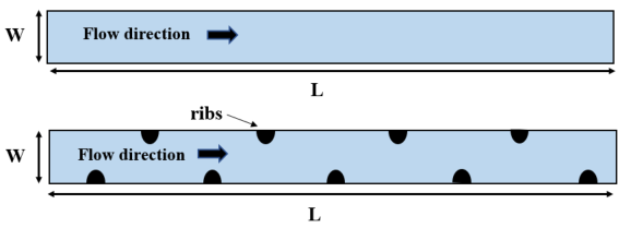
This study investigates microchannels with smooth sidewalls and microchannels incorporating circular ribs on the sidewalls, as shown in Figure 1. A constant heat flux is imposed on both sidewalls of the microchannel. The thermal–hydraulic performance is assessed using the Nusselt number and friction factor, with performance analyzed as a function of the Reynolds number. Each microchannel has a width of 150 μm and a length of 1 cm. Two microchannels are examined: a smooth microchannel and a microchannel featuring semi-circular ribs with a radius of 20 μm and a rib spacing of 1 mm. While previous studies, such as Alnaimat et al. (2023), have explored the influence of manifolds on flow maldistribution, the present analysis assumes uniform flow distribution across all channels.
Figure 1: Diagram of microchannel with smooth and semi-circular ribs.
THEORETICAL MODEL A theoretical model is developed to describe the microchannel configuration illustrated in Figure 1. The governing equations of the model consist of the continuity equation, the Navier–Stokes equations, and the energy equation. Following mathematical modeling proposed by Alnaimat et al. (2024), Equation (1) corresponds to the continuity equation, Equation (2) represents the Navier–Stokes equations, and Equation (3) denotes the energy equation.
Equations and mathematical formulas are available in the original paper PDF.
Thermal Management Using Microchannel 145 Where Vf (m/s) is the the fluid velocity vector, Pf (Pa) is the pressure of the fluid, Tf (K) represents the temperature of the fluid, µf (Pa.s) is the fluid viscosity, ρf (kg/m3) represent the fluid density, kf (W/mK) is the fluid thermal conductivity and Cp,f (J/kgK) is the fluid specific heat capacity. The flow within the microchannel is assumed to be laminar, with negligible heat loss to the surrounding environment and negligible viscous dissipation. A mathematical modeling approach similar to that presented by Alnaimat et al. (2022, 2024, 2025) is adopted in this study. The model incorporates the following boundary conditions: at the microchannel inlet, a specified velocity is imposed and the inlet fluid temperature is fixed at Tf,in = 293; no-slip conditions are applied at all solid walls; the outlet is defined by a zero gauge pressure condition (Pf,out =0). A constant heat flux is applied to the two sidewalls of the microchannel as shown in Equation (5).
µ
Re f f in
The simulations are performed using the Fluent module within ANSYS Workbench. The SIMPLE algorithm is employed for pressure–velocity coupling. After the flow and thermal fields are obtained, the friction factor is calculated using Equations (6). The microchannel’s average heat transfer coefficient, and Nusselt number are calculated using equation (7) and (8) respectively.
(7)
avg
ln T T T T
, , , , / / w out w in f out f in
Where favg denotes the average friction factor, ΔPf (Pa) represents the pressure drop between the inlet and outlet, Nuavg is the average Nusselt number, havg (W/mK) the average heat transfer coefficient in the microchannel. The logarithmic mean temperature difference (LMTD) is defined using the fluid inlet temperature T̅f,in, the fluid’s average outlet temperature T̅f,out, the the temperature of the edges surface at the microchannel’s inlet T̅w,in and at its outlet T̅w,out. The fluid used in the study is water and its thermophysical properties used are (ρ = f 1000 kg/m3, = , p f C 4181 J/kgK, µ = f 0.001006 Pa.s, and = fk = 0.597 W/mK). To investigate the effects of Reynolds number and hydraulic diameter, parametric studies are performed over a Reynolds number range of 100 to 500.
The model is developed based on several assumptions, including steady- state operation, flow within the continuum regime, negligible viscous dissipation, and the absence of phase change during flow. A conventional computational fluid dynamics (CFD) approach is therefore employed without modification, as previous studies have demonstrated the validity of the continuum assumption for microchannel flows.
RESULTS AND DISCUSSION
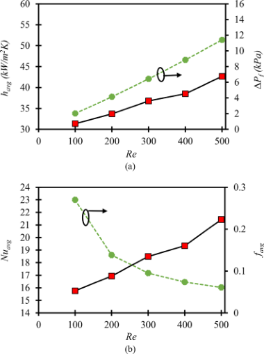
Figure 2(a) presents the variation of the heat transfer coefficient and pressure drop for microchannels with semi-circular ribs over a Reynolds number range of 100 to 500. The heat transfer coefficient is shown on the left vertical axis, while the pressure drop is indicated on the right vertical axis. Figure 2(b) illustrates the relationship between the friction factor, Nusselt number, and Reynolds number for semi-circular-ribbed microchannels over the same Reynolds number range, with the friction factor and Nusselt number plotted on the left and right vertical axes, respectively. As expected, microchannels with semi-circular ribs exhibit increased pressure drops and increased heat transfer coefficients, resulting in increased friction factors and Nusselt numbers. This enhancement in heat transfer at a given Reynolds number is primarily attributed to repeated boundary layer disruption and the formation of secondary flows perpendicular to the main flow direction.
Figure 2: Thermal and hydraulic performance parameters (a) havg and ΔP with Re and (b) Nuavg and favg with Re of semi-circular ribs microchannels (■) havg or Nuavg and (●)
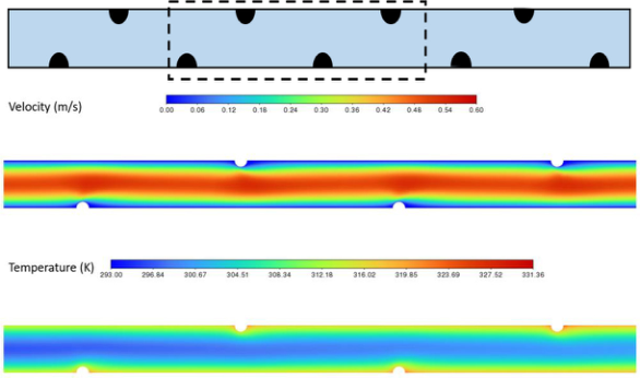
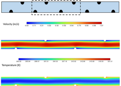
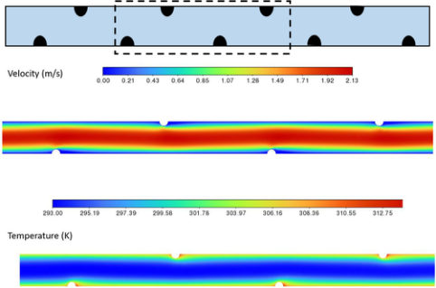
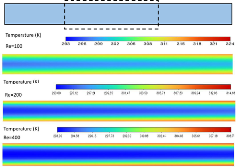
Figures 3, 4, and 5 present the temperature and velocity contours at the mid-plane of the microchannels with semi-circular ribbed surfaces at Reynolds numbers of 100, 200, and 400, respectively. Figure 6 illustrates the temperature contours at the same location for the smooth-surface microchannel at Reynolds numbers of 100, 200, and 400. In both the semi-circular-ribbed and smooth microchannels, the highest temperatures
Thermal Management Using Microchannel 147 are observed at the lowest Reynolds number. The maximum temperature is consistently located near the two sidewalls and after the semi-circular ribs.
A comparison of the velocity profiles for smooth and semi-circular-ribbed microchannels at equivalent axial locations, as shown in Figure 3, indicates that the velocity boundary layer is continuously disrupted by the presence of the semi-circular ribs. As the Reynolds number increases, both the Nusselt number and the heat transfer coefficient increase due to enhanced boundary layer disturbance and the intensification of secondary flows. For all Reynolds numbers considered in this study, microchannels with semi-circular ribs exhibit higher heat transfer coefficients and Nusselt numbers than smooth microchannels, with the performance difference becoming more pronounced at higher Reynolds numbers.
Due to frequent boundary layer disruption and the presence of secondary flows in semi-circular-ribbed microchannels, the associated pressure drop increases with increasing Reynolds number. For a given Reynolds number, the friction factor of the semi-circular-ribbed microchannel is higher than that of the smooth microchannel. It is also observed that the friction factor of circular-ribbed microchannels decreases as the Reynolds number increases. Since the friction factor is directly proportional to the pressure drop and inversely proportional to the average flow velocity, this trend can be explained by the fact that although both pressure drop and average velocity increase with Reynolds number, the rate of increase in flow velocity exceeds that of the pressure drop.
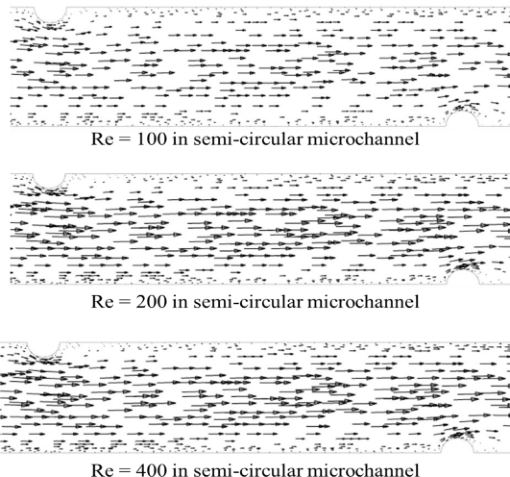
Figure 7 shows the velocity vector plot at location 3 of the semi-circular ribs for Re = 100, 200, and 400. It is noted that the fluid changes directions near the ribs which causes a lateral movement perpendicular to the flow direction around the ribs. This lateral movement cause an improved mixing which enhances the heat transfer coefficient. It is noted that increasing the Reynolds number results in longer vectors which is due to the increased velocity.
Figure 3: Velocity and temperature contour plot at location 1 of semi-circular ribs for Re = 100 (Dhy = 300 µm, L = 1 cm).Figure 4: Velocity and temperature contour plot at location 1 of semi-circular ribs for Re = 200 (Dhy = 300 µm, L = 1 cm).Figure 5: Velocity and temperature contour plot at location 1 of semi-circular ribs for Re = 400 (Dhy = 300 µm, L = 1 cm).Figure 6: Temperature contour plot at location 1 of smooth channel for Re = 100, 300, 500 (Dhy = 300 µm, L = 1 cm).Figure 7: Vector plot of at the middle of the channel of semi-circular ribs for Re = 100, 200, and 400 (Dhy = 300 µm, L = 1 cm).
CONCLUSION
The thermohydraulic performance of microchannels equipped with semi- circular ribs under steady heat flux conditions is systematically investigated in this study. Performance is evaluated over a Reynolds number range of 100 to 500 using key parameters, including the friction factor, Nusselt number, heat transfer coefficient, and pressure drop. The results reveal that semi-circular-ribbed microchannels exhibit higher friction factors, pressure drops, heat transfer coefficients, and Nusselt numbers compared to smooth microchannels. Additionally, the influence of the Reynolds number on the performance of both semi-circular-ribbed and smooth microchannels is analyzed, showing that increasing the Reynolds number leads to simultaneous increases in pressure drop and heat transfer coefficient.
ACKNOWLEDGMENT
The authors acknowledge funding from United Arab Emirates University through grant (#12R231 and #12R307).
REFERENCES
Almehisni R., Alnaimat F., Heat Transfer Influence of Solar Panel on Spacecraft, Advances in Engineering Technology & Sciences Multi-Conferences (ASET 2018), Feb. 6–7, 2018. Alnaimat, F, Daadoua, M., Mathew, B., Effect of pin fins on heat transfer
during condensation in minichannel heat exchanger, International journal of Thermofluids, 2024, 100917. Alnaimat, F., Mathew, B. (2023) “Flow distribution in microchannel devices with U-shaped manifolds,” International Journal of Thermofluids, vol. 19, p. 100391. Alnaimat F., El Kadi K., Mathew B., CFD investigation of R134a and Propane
condensation in square microchannel using VOF model: parametric study using steady state solution, Journal of thermal science and engineering progress, 2023, 38, 2451-9049. Alnaimat F., Ziauddin M., Experimental investigation of Heat Transfer in Pin-fins heat sinks for cooling application, Journal of Heat and Mass Transfer, 2020, 1–7, Alnaimat, F, Ahmad Rahhal, Mathew, B., Fluid flow and heat transfer investigation
of microchannel heat sink with sidewall triangle pin-fins, Int. J. of Thermofluids, 2025, 101141. Daadoua M., Mathew B., Alnaimat F., Experimental investigation of pressure drops and heat transfer in minichannel with smooth and pin fin surfaces, International journal of Thermofluids, 2024, 21, 100542. El Kadi K., Alnaimat F., Sherif S.A, Recent advances in condensation heat transfer in
mini and micro channels: A comprehensive review, Applied Thermal Engineering, 2021, 117412. Steinke, M.E. & Kandlikar, S. G. (2004), Review of Single-Phase Heat Transfer Enhancement Techniques for Application in Microchannels, Minichannels and Microdevices, International Journal of Heat and Technology, 22, 3–11. Sui, Y., Teo, C.J., Lee, P.S., Chew, Y.T., Shu, C. (2010), Fluid Flow and Heat Transfer
in Wavy Microchannels, Int. Journal of Heat and Mass Transfer, 53, 2760-2772. Varghese D., Alnaimat F., Mathew B., Characteristics of MEMS Heat sink using Serpentine Microchannel for Thermal Management of Concentrated Photovoltaic Cells, IEEE Access, 2023, 10483–10498. Zheng, Z., Fletcher, D.F. & Haynes, B.S. (2013), Chaotic Advection in Steady Laminar
Heat Transfer Simulations: Periodic Zigzag Channels with Square Cross-Sections, International Journal of Heat and Mass Transfer, 57, 274–284. Zheng, Z., Fletcher, D.F. & Haynes, B.S. (2013), Laminar Heat Transfer Simulations for Periodic Zigzag Semicircular Channels: Chaotic Advection and Geometric Effects, International Journal of Heat and Mass Transfer, 62, 391–401.
LISTED IN THE AHFE DIGITAL BOOKSTORE CATALOGUE
Explore the complete digital volume
Human Error, Reliability, Resilience, and Performance
Read this individual research paper free through the original publisher, or explore the full digital proceedings book.
ISBN 978-1-964867-89-2
Explore this ISBN in the AHFE Bookstore ↗Listed in the July 2026 bookstore catalogue; search by ISBN to confirm current availability · Digital book purchase optional