Jun Li, Xuejiao Sun, Hejin Gu, Xingyao Su, Jifang Wang (2023). Framework for Defining the Perspectives of the 3D Driving Visualization Interface for Driving Automation System-Engaged Vehicles. In: Human Interaction & Emerging Technologies (IHIET 2023): Artificial Intelligence & Future Applications. AHFE Open Access, vol. 111, pp. 324–332. https://doi.org/10.54941/ahfe1004039
3D driving visualization is a crucial component of in-car Human-Machine Interface (HMI), as it effectively conveys the behavior and intention of driving automation system-engaged vehicles. However, the performance of 3D interface information transmission is significantly affected by perspectives. This paper presents a perspective definition framework based on overall cockpit interaction. It discusses the factors that affect 3D perspective definition in driving scenarios and how they impact it.
Advancements in sensor technology and artificial intelligence have improved driving automation in recent years. However, most passenger vehicle automa- tion systems range from the SAE Level 2 to Level 3 (SAE International/ISO, 2021). These systems require high transparency, which is difficult to achi- eve in situations with low cognitive participation (Alonso and De La Puente, 2018). Moreover, the technical logic governing driving automation is frequ- ently abstract, and manufacturers may implement different logic and design domains for their systems, leading to challenges in visually conveying the system’s state and behavior.
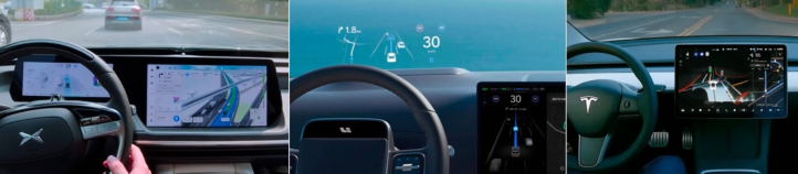
Compared to 2D displays, 3D driving visualizations based on 3D engi- nes can display more real-time information about the ego car’s status and surrounding environment. As a result, vehicles equipped with L2 or higher driving automation systems have integrated 3D driving visualizations on scre- ens such as instrument panels, central consoles, or heads-up displays (HUDs) (see Figure 1). These visualizations enable drivers to verify the system’s capa- bilities, comprehend the vehicle’s behavior, and reduce their anxiety and distrust of the system.
The perspective of the 3D driving visualization interface, which refers to the angle and range of the view, has a direct impact on the effectiveness of dri- ving situation information. While some established practices consider typical perspectives, theoretical research and design recommendations remain rela- tively scarce. This paper aims to provide an overview of perspective design
Framework for Defining the Perspectives of the 3D Driving Visualization Interface 325
Figure 1: A collection of images showing the current 3D driving visualizations of vehicles equipped with driving automation systems.
for 3D driving visualization interfaces based on overall cockpit interaction. It covers topics such as the construction of 3D visualization interfaces, factors that affect perspective definition, and suggestions for perspective definition for different driving scenarios.
PERSPECTIVES OF DRIVING VISUALIZATION INTERFACE 3D Driving Visualization Interface Construction
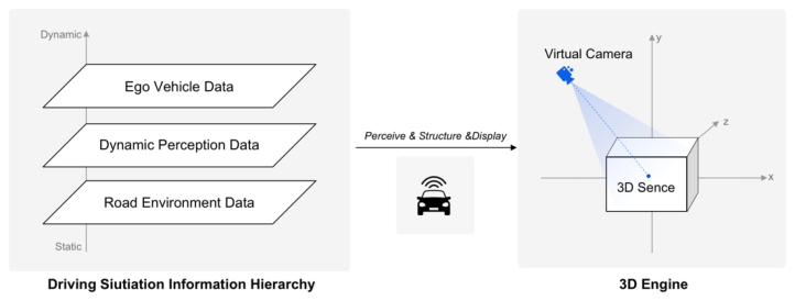
3D driving visualization is a type of visual display that uses a construction logic (see Figure 2). In the process of automated driving, sensors mounted on the vehicle, such as visual cameras, lidar, and millimeter-wave radar, perceive the external environment in real-time. These sensors combine with GPS posi- tioning to return data on the attributes (location, direction, distance) of the perceived object. These data can generally be summarized into the following three levels, from static to dynamic:
Road environment data, including road topology structure, lane lines, and surrounding buildings.
Dynamic perception data, such as other vehicles, pedestrians, cones, and other obstacles on the road.
Ego vehicle data, including current behavior (changing lanes, acceleratio- n/deceleration, stopping, etc.) and next intention (about to enter the ramp, to change lanes, etc.).
Figure 2: The construction logic of the 3D driving visualization interface.
Static information primarily refers to physical, real-world information that typically changes less over time, such as road structures, lanes, and surroun- ding buildings. This information can be collected in advance and provided as High Definition (HD) Maps, which can then be integrated into high-level driving automation systems (Liu, Wang & Zhang, 2020). On the other hand, dynamic information refers to data that is difficult to predict and preset, and can only be perceived during the driving process.
To design such an interface, the designer should first understand the infor- mation hierarchy and current sensor accuracy, including the type and size of sensors. With this knowledge, the designer can define the visual style of the 3D scene and prepare the corresponding 3D model. During driving, the system gathers real-time data from sensors, matches it with preset 3D models, maps the corresponding position coordinates in the 3D engine, and constru- cts a 3D driving visualization scene. Finally, this scene is displayed to the driver in a specific view.
Canonical Views of 3D Scenes The Field of View (FOV) where the human eyes overlap is about 114
hori- zontally and 180
vertically (Rahul, 2022). Therefore, the driver can only observe a specific angle in the 3D scene at a particular moment. Thus, it is desirable for the system designers to provide the most canonical view of the 3D scene. Specifically, the general public prefers canonical views, which are the views that first come to mind when an object is mentioned. These views are considered to have the most aesthetic value and to carry enough typical features of the object to provide sufficient information (Blanz et al., 1999).
Individuals may have distinct preferences for canonical views in static obje- cts, static scenes, and dynamic scenes. The following guidelines can be applied to each category:
Static objects: Use a side view with a slight horizontal tilt and minimal ver- tical offset to show the most visible surface area and information (Higgins, 2011).
Static scenes: Use a vertically oriented top view without horizontal offset to understand the global state and spatial orientation of the scene (Higgins, 2011).
Dynamic scenes: Use a view that maximizes the spatial changes between multiple objects. For racing games, a line of sight angle perpendicular to the motion axis is preferred to better observe the positional relationship of different objects (Garsoffky et al. 2009).
Driving visualization is a typical dynamic scene that requires maximi- zing the spatial relationship between the vehicle, surrounding vehicles, roads, and other objects. However, it should be noted that driving visualization is not only used for observation, but also to assist users in completing speci- fic driving tasks. Therefore, an observation perspective perpendicular to the direction of motion is unsuitable. Instead, a top-down perspective that fol- lows the vehicle is commonly used in typical cruising scenarios to enhance immersion.
Framework for Defining the Perspectives of the 3D Driving Visualization Interface 327
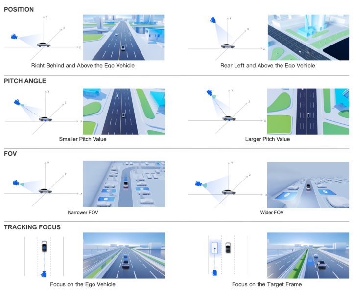
Virtual Camera Parameters of Perspective Definition 3D driving visualization interfaces are usually developed using 3D engines like Unity, Unreal Engine, and OpenGL. By adjusting the virtual camera’s parameters in the 3D engine, we can obtain the corresponding viewing range and angle on the display interface. Although the perspective definition para- meters of different engines vary, they can generally be summarized into four types (see Figure 3):
Position: The position of the camera in the 3D world is defined by its coor- dinates (x, y, z). Adjusting the camera position changes the observation angle and object size while keeping other parameters constant. In driving visualization scenes, the ego vehicle is typically used as the origin of the 3D world coordinates, and the camera is positioned to observe the ego vehicle from different horizontal and vertical distances.
Orientation: The direction of camera observation is defined by the rota- tion angle of the camera relative to the x, y, z axis. In driving scenarios, the pitching angle (pitch) is commonly used. The larger the pitch angle, the closer the view is to the top view and the more accurate the relative dista- nce between multiple objects. Conversely, the smaller the pitch angle, the stronger the depth of the view, but the distance in the forward direction will be shortened.
Figure 3: The impact of adjusting virtual camera parameters on perspective.
FOV: The FOV determines the extent of the observable scene. A wider FOV provides a stronger perspective, but may cause visual discomfort. The appropriate FOV should be chosen based on the scene size. A wider FOV is appropriate for a wide and large scene, while a relatively narrower FOV should be set for a small scene. Once the FOV is set, it should be kept constant during observation to prevent motion sickness.
Tracking Focus: The camera dynamically observes the tracked target. In driving visualization, the camera usually tracks the ego-vehicle, but it can also shift slightly in specific scenes. For example, when changing lanes, the tracking focus can be placed on the target placement frame that moves with the vehicle.
3 PERSPECTIVE DEFINITION FRAMEWORK
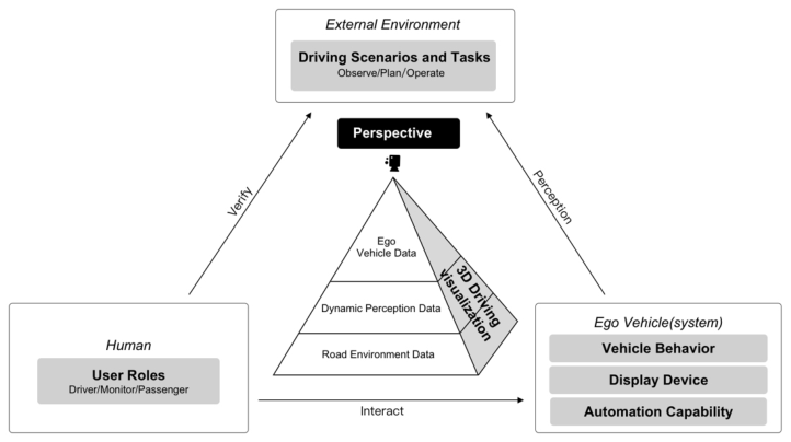
This paper presents a framework for defining perspectives in 3D driving visualization interfaces (see Figure 4). The framework is based on the human- vehicle-environment system and summarizes the factors that impact perspe- ctive definition. Additionally, it provides recommendations corresponding to these factors, serving as a foundation for future research.
User Roles The role of the driver in an automated vehicle depends on the enabled state of the automated system. Different role positions have different focuses on driving:
When driving manually, the driver needs to quickly establish spatial and orientation relationships around the ego vehicle. Therefore, it is best to use the cruise camera position following the ego vehicle.
Figure 4: Perspective definition framework based on the human-vehicle-environment system.
Framework for Defining the Perspectives of the 3D Driving Visualization Interface 329
When the automated system is enabled, the system is responsible for Object and Event Detection and Response (OEDR), and the driver needs to monitor the car’s driving by getting a preview of the trip. Therefore, the camera position will be further away than before.
In the fully automated driving state, the user role is that of a passenger, and more attention is paid to trip information. The camera position for the passenger screen in the car is relatively high and overlooks to show more global information.
Driving Scenarios and Tasks Driving scenarios are dynamic and complex, involving many tasks and operations. Different driving tasks require specific information about the sur- rounding environment and blind spots. It is important to match the type of information to the driver’s tasks, needs, and expectations as much as possi- ble to enhance performance and understanding (Campbell et al., 2018). For instance:
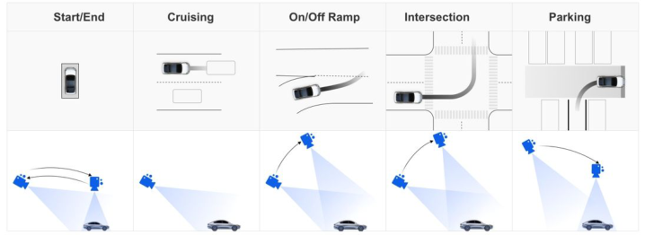
During regular cruising, drivers need to focus on the forward field of vision and maintain a safe following distance from the vehicle in front. Accor- ding to the widely accepted “3-second rule,” drivers should aim to have a reaction time of at least 3 seconds to reduce the risk of rear-end collisions. As vehicle speed increases, the camera should be positioned further and higher to provide a broader view.
In complex traffic environments such as intersections, the scene can be more complicated, and drivers need to pay attention to pedestrians and other road users in multiple directions. To achieve this, it may be appro- priate to increase the pitch angle, reduce environmental distractions such as the sky, and emphasize the road surface information.
During intelligent parking, the user needs to follow the system’s guidance to interact with the human interface. The perspectives should facilitate the distinction and guidance of different scenarios, and the size of the interactive area in the interface should also be considered.
Figure 5: Recommended perspectives for different driving scenarios.
Therefore, during the driving process, a single perspective may not meet all information requirements. It is necessary to dynamically adjust the perspe- ctive according to specific triggering factors to enhance observation and operation requirements, and to improve system transparency and operability (see Figure 5).
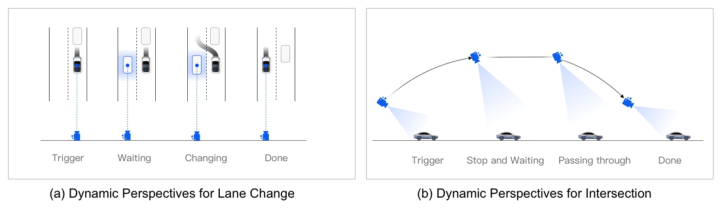
Vehicle Behavior Vehicle behavior refers to how a vehicle reacts to different driving conditions and situations. According to Fogg’s Behavior Model (Fogg, 2009), humans need motivation, ability, and a trigger to perform a behavior. Similarly, for a vehicle with a driving automation system to execute a driving behavior, these elements are also crucial. To improve users’ understanding of the vehicle’s behavior, dynamic perspective changes can be used to highlight the different stages of the behavior and communicate information more effectively. For example:
Figure 6: Dynamic perspective changes for lane change and intersections.
When a vehicle needs to change lanes (see Figure 6a), it must assess the traffic situation both before and after the target lane. To achieve this, we can pan the camera towards the target lane, with the target location frame serving as the tracking focus. Raising the camera to display more side-rear information can also reduce the distance deviation caused by perspective. During the lane change, the vehicle will perform lateral movement, and we can maintain the camera position. After the lane change, we can return to the normal cruising perspective.
When a vehicle passes through an intersection (see Figure 6b), it may encounter triggering factors, such as a red light, which will cause the veh- icle to slow down and stop. While stopped and waiting, we can raise the camera to display more intersection information. This camera position can be maintained continuously throughout the process of passing through the inter- section. After passing through the intersection, the camera can be returned to the cruising perspective.
Display Device The driver typically uses the visualization interface via the cockpit screens. Therefore, the placement of the visual display can significantly affect the driver’s ability to gather information efficiently. The design of the driving information should aim to minimize the amount of time the driver’s eyes are
Framework for Defining the Perspectives of the 3D Driving Visualization Interface 331
off the road and reduce any negative effects on driving performance (Camp- bell et al. 2018). Common display devices in vehicles include the instrument panel and central console. The instrument panel display is designed to pro- vide information about the vehicle’s surroundings during manual driving, while the central console display is mainly used for human-vehicle co-driving. The camera view on the central console is located farther away to provide additional route navigation information.
In addition to location, the display ratio of the visualization interface also affects the perspective. The aspect ratio of the camera view should be consi- stent with the proportion of the display area. For horizontal screen displays, utilize the longitudinal distance to display more route information. The sky- line can be positioned higher to reduce the ambient atmosphere. For vertical screen displays, increase the height to provide more environmental displays and enhance the sense of space.
Automation Capability Automation capabilities mainly refer to the perceived range and accuracy of autonomous driving sensors, as well as the construction method of 3D scenes.
When defining the overall display scope, it is important to consider the perceptual range and construction method of the 3D scene to avoid an unre- asonable layout. If the scene is entirely constructed from real-time perception data, adjust the perspective according to the actual perception range to ensure a reasonable display. If the road environment scene is constructed from an HD map, the screen will not be blank, but it is also necessary to consider the location of the ego car according to the perception range.
When designing dynamic perspective switching, it is crucial to consider the accuracy of perception. If a triggering factor for perspective switching (such as encountering an obstacle) is not recognized accurately, it is better to avoid making dynamic changes in perspective based on it to prevent causing discomfort or dizziness for the viewer.
CONCLUSION AND FUTURE WORK This paper proposes a framework for defining perspective based on the human-vehicle-environment system. When defining perspective, we must consider the human factors of display devices, user roles, and autono- mous driving system capabilities. For dynamic perspectives, special attention should be paid to analyzing driving tasks and communicating the ego car’s behavior. Based on our analysis, we have summarized the following design recommendations to provide basic guidance for perspective definition:
Meet the observation/operation needs of a specific driving scenario to improve the transparency and operability of the system.
Meet the basic human factors requirements of in-car visual display, such as recognition efficiency and smallest operable size.
Provide a canonical view of driving scenes to avoid driving distractions caused by the user’s manual adjustment of the screen. If adjustment is required, it is recommended to control the degree of freedom.
Control the number of perspectives and the frequency of dynamic switch- ing to avoid causing viewer dizziness.
Using the framework and design recommendations, we can establish eva- luation standards for 3D driving visualization perspectives. We can then conduct quantitative experimental research to measure the effect of spe- cific perspective definitions on driving situations and system transparency enhancement. Furthermore, we will develop perspective definition strategies tailored to special driving scenarios, particularly those encountered in urban driving.
REFERENCES
Alonso, V. and De La Puente, P., 2018. System transparency in shared autonomy: A mini review. Frontiers in neurorobotics, 12, p. 83. Blanz, V., Tarr, M. J. and Bülthoff, H. H., 1999. What object attributes determine
canonical views?. Perception, 28(5), pp. 575–599. Campbell, J. L., Brown, J. L., Graving, J. S., Richard, C. M., Lichty, M. G., Bacon, L. P. and Sanquist, T., 2018. Human factors design guidance for level 2 and level 3 automated driving concepts (No. DOT HS 812 555). Fogg, B. J., 2009. A behavior model for persuasive design. In Proceedings of the 4th
International Conference on Persuasive Technology, pp. 1–7. Garsoffky, B., Schwan, S. and Huff, M., 2009. Canonical views of dynamic scenes.
Journal of Experimental Psychology: Human Perception and Performance, 35(1), pp. 17. Higgins, J., 2011. Canonical views of objects and scenes. University of Illinois at Urbana-Champaign. Liu, R., Wang, J. and Zhang, B., 2020. High definition map for automated driving:
Overview and analysis. The Journal of Navigation, 73(2), pp. 324–341. Rahul Awati., 2022. Field of view (FOV). TechTarget [Online] Available at: https: //www.techtarget.com/whatis/definition/field-of-view-FOV. SAE International/ISO., 2021. SAE J3016: Taxonomy and Definitions for Terms
Related to Driving Automation Systems for On-Road Motor Vehicles.
Read this individual research paper free through the original publisher, or explore the full digital proceedings book.
ISBN 978-1-958651-87-2
Explore this ISBN in the AHFE Bookstore ↗Listed in the July 2026 bookstore catalogue; search by ISBN to confirm current availability · Digital book purchase optional