Ahmad Abbasi, Andrea Zanoni (2026). Redesign of an optical force sensor for hand-grip interface in helicopter flight simulators. In: Human Systems Engineering and Design (IHSED2026): Future Trends and Applications. AHFE Open Access, vol. 237, pp. 803–809. https://doi.org/10.54941/ahfe1008218
The iterative redesign of a product is essential for advancing its Technology Readiness Level, enabling the transition from conceptual prototypes to reliable, real-world applications. In this study, a tactile force sensor named OPT-IN (OPTical-INceptor) based on the optical phenomena of Frustrated total internal reflection (FTIR) is redesigned as a product to be utilized on helicopter flight simulators as a collective controller. The sensor design includes light detectors, an LED light source, hemispherical silicone probes and a waveguide for transmitting light. The redesigned tactile sensor focuses on minimizing optical losses and measurement bias by reducing light leakage to the light sensing elements through properly shielding the waveguide and optimizing the LEDs placement for efficient signal transmission. Mechanical stability was improved through secure positioning of the photodetectors and probes, along with an ergonomic probe holder designed to improve user interaction. Additionally, cable management and structural integration were refined to enhance signal stability and overall system reliability. Finally, experimental tests involving two manoeuvres: a vertical repositioning and an Acceleration-Deceleration are conducted on an research flight simulator to evaluate the sensor’s performance in field applications.
Human–machine interaction is key to maintaining safe and efficient system control. As the level of automation increases, the operator’s role becomes even more critical. This highlights the importance of a reliable Human- Machine-Interface systems; hence, continuous system redesign is necessary to improve usability and enhance the efficiency of the final product. At the same time, technology readiness ensures that these redesigned solutions are reliable and effective in real-world applications.
Technology Readiness Levels (TRLs) offer a structured method for evaluating how mature a technology is, progressing from fundamental scientific concepts to fully functional systems (Mankins, 1995). The index is now considered and industrial standard, and it is not difficult to find instances of successful application. For illustrative purposes, one can consider an example involving the redesign of a gripper sensor—specifically the ME450 Received April 22, 2026 Revised June 27, 2026 Accepted July 14, 2026 Available online September 25, 2026
804 Abbasi and Zanoni nitinol gripper—used in middle ear prostheses to enhance its performance. After assessing its advantages and limitations, the author determined that the gripper material must be biocompatible, safe for patients, compatible with MRI environments, compact enough to accommodate an accelerometer within the confined space of the middle ear, and etc (Barry, 2023). In a separate study, researchers introduced an innovative design for a compact and lightweight six-axis force/torque sensor intended for legged robots. This design emphasizes ease of manufacturing and cost efficiency, while also incorporating new calibration techniques that streamline the process and reduce required effort (Kim, 2023). Similarly, another study demonstrated that redesigning a product can significantly lower costs. Bin Ahmad et al. improved the design of a water nozzle to enhance efficiency while reducing production expenses. A comparison between the original and redesigned versions showed that the updated design used fewer components, leading to reduced costs, shorter assembly times, and more efficient operation (Bin Ahmad et al., 2018).
This paper focuses on redesigning a tactile force sensor for use in helicopter flight simulators, aiming to improve performance aspects such as signal stability and overall functionality. The paper is structured as follows: the Optical-Inceptor section examines the sensing principle, outlines the components used in the sensor, and describes the hardware. Various aspects of the proposed design are then discussed. In the experimental demonstration section, the manoeuvres used to evaluate the sensor’s performance are defined. Finally, the results and conclusions are presented.
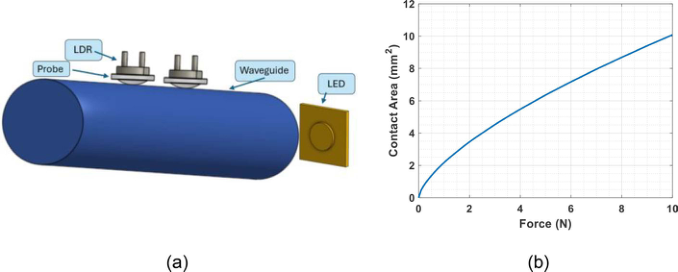
Figure 1: a) OPT-IN components. b) hertz contact theory application results yielding the contact area between a spherical probe and the cylindrical waveguide for speci fied dimensions.
OPTical - INceptor (Sensing Principle, Components, Sensor Design and Hardware) OPT-IN is an optical force sensor, based on the principle of Frustrated Total Internal Reflection (FTIR) (Lavatelli et al., 2018). This phenomenon occurs when light that would normally undergo total internal reflection in a medium
Redesign of an Optical Force Sensor for Hand-Grip Interface 805 is partially transmitted into another nearby medium if the second is brought sufficiently close to the surface of the first. As a result, some of the light “leaks” across the boundary instead of being fully reflected.
In this design, light propagates through a polycarbonate waveguide where it remains confined. When a silicone probe is pressed against the waveguide, a portion of the light can travel into the probe. The amount of transmitted light depends on the contact area between the probe and the waveguide. This light is then detected using a light-sensitive component such as a light-dependent resistor (LDR). The sensor itself consists of simple components, including an LED, the waveguide, the silicone probe, and the LDR (see Figure 1a) (Zanoni et al., 2023). The intensity of the detected light is directly related to the contact area between the probe and the waveguide. Furthermore, the relationship between the applied force and the resulting contact area—formed between the spherical probe and cylindrical waveguide—can be described using Hertzian contact theory (Barber, 2018). As shown in Figure 1b, the force–contact area curve is initially nonlinear but becomes approximately linear beyond for higher values of the applied force.
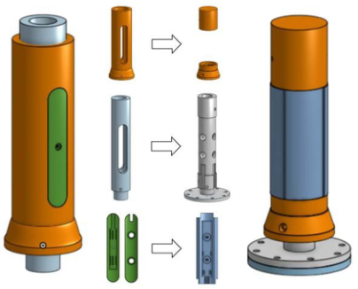
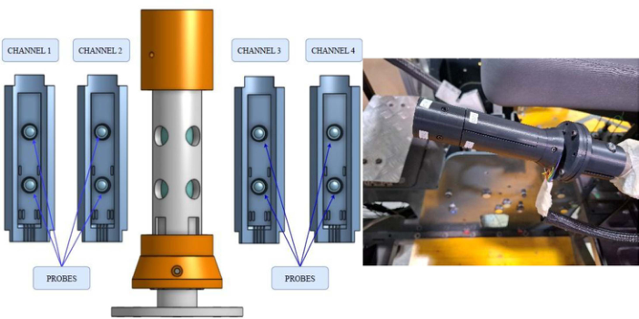
The sensor is designed to achieve several objectives. First, it minimizes light leakage into the surrounding environment. Since the sensing mechanism relies on optical effects, the waveguide is fully enclosed, with only small circular openings that allow the silicone probes to press against it. Another important consideration is maintaining a stable position for the LDR. Light detectors are sensitive to the angle of incident light, and even small angular variations can significantly affect the measured intensity. To ensure consistent readings, the LDR is fixed securely in place using a dedicated holder and adhesive. The silicone probe is similarly fixed directly in front of the LDR. Wire management is also carefully addressed to prevent interference with sensor performance. Small internal channels are incorporated into the probe holders to keep the wires neatly secured. Additionally, structural barriers are included at the top and bottom of the probe holders and they are compressed by the top and bottom objects of the sensor. These are designed with precise dimensions to apply a small preload to the probes, slightly compressing them. This helps eliminate the initial nonlinear region of the force–contact area relationship. Figure 2 shows the previous OPT-IN design vs the redesigned one. It indicates that parts evolving through redesign process. Figure 3 illustrates the overall sensor design for the collective controller of the rotor pilot coupling (RPC). The LED is positioned at the bottom of the sensor assembly. There are 4 Channels (probe holders), each channel contains 2 LDRs, one is at the top of probe holder and one at the down.
Figure 2: The previous design at the left side vs the redesigned one at the right side.Figure 3: OPT-IN design for the collective lever.
In summary, the OPT-IN hardware is composed of several key components. An STM32 microcontroller board(NUCLEO-F072RB) handles data acquisition and is powered by a portable power bank. A voltage booster is used to supply sufficient voltage to power the LED, which requires 8 V to operate. Next, a voltage divider circuit is implemented for the LDRs (in total 8 LDRs) to enable signal measurement. An SD card module is included to store the acquired signal data.
EXPERIMENTAL DEMONSTRATION An important component of the human systems integration plan should be a verification and validation process that provides a clear way to evaluate the success of human systems integration. Hence, two manoeuvres named Acceleration -Deceleration and Vertical Repositioning are chosen from ADS33 (Aviation, U.A., 2000) to be performed with the help of a research simulator, the RPC test bed at Politecnico di Milano DAER laboratories (Zanoni et al., 2022).
Redesign of an Optical Force Sensor for Hand-Grip Interface 807 The acceleration–deceleration manoeuvre starts from a stabilized hover. The pilot quickly increases power to near maximum to begin accelerating forward, while keeping altitude constant using pitch control. During the acceleration, the collective is kept constant until the aircraft reaches 50 KIAS. After reaching this speed, the pilot reduces power sharply to initiate deceleration. Altitude is maintained throughout using pitch adjustments. As the aircraft slows down, the nose is raised to reduce speed. The maximum nose-up attitude occurs just before returning to a stable hover, completing the manoeuvre.
The vertical repositioning manoeuvre was used to study Rotorcraft Pilot Coupling (RPC) related to rotor coning and heave control using a simplified 2-DOF flight model. Test criteria were based on ADS-33E-PRF standards, adapted at the FRAME Lab of Politecnico di Milano. The manoeuvre simulated a rapid unmask/remask scenario, requiring the pilot to aim at the unmasked position. Starting from a hover at 15 ft AGL, the rotorcraft ascended to 40 ft AGL, hovered for at least 2 seconds, and then descended back to 15 ft AGL. After completing terminal station-keeping, a landing was performed to evaluate coupling effects with including possible effects of the landing gear dynamics and the ground contact. The test course included ground markings to define performance zones. Trials were conducted under varying turbulence and collective gear ratio conditions to assess RPC behaviour.
RESULT
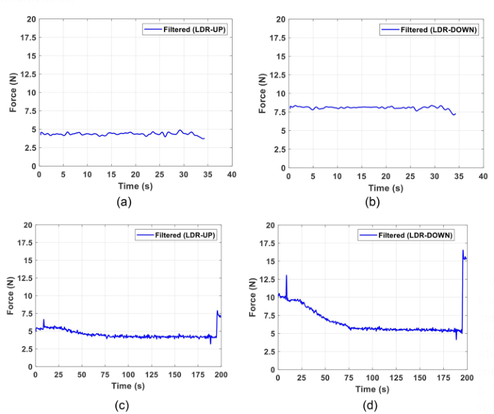
The FTIR-based tactile sensing system was evaluated using two LDR sensors (UP and DOWN) mounted in a probe holder under two conditions: acceleration/deceleration (top row) and vertical repositioning (bottom row). Figure 4 shows the response of channel 3, illustrating the sensor’s dynamic behaviour. This setup enables the assessment of both transient and steady- state responses, providing insight into the system’s reliability under different motion conditions. During acceleration/deceleration, both sensors produce stable signals with minimal fluctuations despite rapid inputs. No motion- induced disturbances such as lag, vibration, or overshoot are observed, and the absence of significant peaks confirms a smooth response. Such stability is important for accurate sensing under fast-changing conditions. In the vertical repositioning manoeuvre, slight vibrations introduce initial noise in the signal. However, after filtering, the signal becomes smooth and consistent, highlighting the effectiveness of signal processing. The slower response suggests a stronger influence of quasi-static forces, consistent with FTIR sensing where contact area changes dominate the output.
Overall, the sensor maintains a smooth and stable response in both manoeuvres, without noticeable lag or sudden peaks. These results demonstrate robustness during fast motions and improved sensitivity during slower, controlled interactions.
Figure 4: Responses of channel 3 a) acceleration-deceleration LDR-UP b) accelera tion-deceleration LDR-DOWN c) vertical repositioning LDR-UP d) vertical reposition ing LDR-DOWN.
CONCLUSION
This study is conducted to increase the TRL of a force sensor named OPT-IN from TRL3 to TRL6. The redesign was carried out with several key objectives in mind. First, it prevents unwanted light emission; the updated design blocks stray light, which improves signal stability. Second, it secures the positions of both the LDR and the probe, as they are now fixed to the probe holder using adhesive. Another improvement involves wire management, with the wiring arranged to ensure smooth and reliable sensor operation. Additionally, barriers have been added at the top and bottom of the probe holder to apply a preload to the probes.. e. At the end, designing and performing some experimental study prove the reliable, robustness application and performance of redesigned force sensor. In addition, further experiments will be conducted using other facilities, such as an aircraft simulator, as part of future development efforts to evaluate pilot workload based on OPT-IN signal responses.
ACKNOWLEDGMENT
The authors acknowledge the use of ChatGPT (OpenAI) as a language assistance tool to improve the readability and clarity of this manuscript. The authors take full responsibility for the content of the paper, including all analyses, interpretations, and conclusions.
REFERENCES
Aviation, U.A., 2000. Missile Command Aviation Engineering Directorate. Aeronautical Design Standard, Performance Specification, Handling Qualities Requirements for Military Rotorcraft. Barber, J.R., 2018. Contact mechanics (Vol. 20). Berlin: Springer International Publishing. Barry, C.J., 2023. Re-design & Fabrication of Sensor “Gripper” For Use in Middle
Ear Prosthesis. Bin Ahmad, M.N., Arep, H., Maidin, N.A., Rahman, M., Hidayat, A.B., Wahid, M.K. and Osman, M.H., 2018. Reducing Product Cost by Implementing DFMA Methodology-Lucas Hull: A Case Study. ESTEEM, 14. Kim, H.B., Choi, K.H. and Kim, K.S., 2023. A compact optical six-axis force/torque
sensor for legged robots using a polymorphic calibration method. arXiv preprint arXiv:2309.04720. Lavatelli, A., Zanoni, A., Zappa, E. and Cigada, A., 2018. On the design of force sensors based on frustrated total internal reflection. IEEE Transactions on Instrumentation and Measurement, 68(10), pp. 4065–4074. Mankins, J.C., 1995. Technology Readiness Levels: A White Paper. Advanced
Concepts Office, Office of Space Access and Technology, NASA [online] Zanoni, A., Garbo, P., Masarati, P. and Quaranta, G., 2023. Frustrated Total Internal Reflection Measurement System for Pilot Inceptor Grip Pressure. Sensors, 23(14), p. 6308. Zanoni, A., Marchesoli, D., Talamo, C., Masarati, P., Colombo, F., Kemp, S. and
Fosco, E., 2022. Experimental test-bed for the identification of biodynamic feedthrough of helicopter-pilot systems. In 48th European Rotorcraft Forum (ERF 2022) (pp. 1−12). Curran.
FIND THE COMPLETE VOLUME IN THE AHFE DIGITAL BOOKSTORE
Explore the complete digital volume
Human Systems Engineering and Design (IHSED2026): Future Trends and Applications
Read this individual research paper free through the original publisher, or explore the full digital proceedings book.