Pierre Garbo, Andrea Zanoni, Giuseppe Quaranta (2021). An optical pressure measurement system for control inceptors to evaluate pilots’ workload. In: Human Systems Engineering and Design (IHSED2021): Future Trends and Applications. AHFE Open Access, vol. 21. https://doi.org/10.54941/ahfe1001154
Understanding human-machine interaction is a fundamental research area in all engineering disciplines were the interaction between the user and the vehicle is central. From this point of view, aircraft in general and helicopters specifically offer a challenging test-bench: the interaction between the pilot and the helicopter is crucial tothe success of the flight missions. Furthermore, in some cases, the unwanted feedthrough of the aircraft accelerations at the control inputs can lead to adverse feedback loops, known as Rotorcraft Pilot Couplings (RPC) [1,2]. Since the pilot input is mediated by the control inceptors, measuring the pressure that the pilot’s hands exert on the inceptors’ grip can be very important in evaluating the mechanical impedance of the pilot, which can be correlated to the task workload [3]. However, Embedding existing measurement hardware inside the control inceptors grips may be challenging, or even impossible, without significantly altering the grip layout and thus introducing a possible source of discomfort for the pilot. These limits spurred the need to develop new measurement systems, that is able to - provide a reliable signal correlated to force exchanged between the hand and the grip; - be easy to be manufactured in such a way to be embedded in the grip, with as little loss in ergonomics as possible; - provide a signal that requires as little conditioning as possible.The solution proposed in this work has been called OPT-IN FCS (For OPTical-INceptors Flight Control System, Patent Pending) and is based on a well-known physical phenomenon commonly referred to as Frustrated Total Internal Reflection (FTIR). When an optical wave-guide, in which total internal reflection occurs, comes into contact with a third medium (outside of the wave-guide itself and air) a fraction of the incident radiation can propagate through the third medium. The paper will present the design and manufacturing of a full prototype of this device embedded in a control stick, and its application to a desktop simulator to monitor the hand activity for pilots during the performance of tasks with different levels of workload.[1] M.D. Pavel, M. Jump, B. Dang-Vu, P. Masarati, M. Gennaretti, A. Ionita, L. Zaichik, H. Smaili, G. Quaranta, D. Yilmaz, M. Jones, J. Serafini, J. Malecki (2013). Adverse rotorcraft pilot couplings—Past, present and future challenges, Progress in Aerospace Sciences, Vol. 62, 2013, Pages 1-51.[2] Quaranta, G., Masarati, P., Lanz, M., Marforio, M., & Muscarello, V. (2014). Biodynamic Adverse Rotorcraft-Pilot Coupling. In 5th International Conference on Applied Human Factors and Ergonomics (AHFE 2014), pp. 87-96.[3] Zanoni, A., Zago, M., Paolini, R., Quaranta, G., Galli, M., & Masarati, P. (2021). On Task Dependence of Helicopter Pilot Biodynamic Feedthrough and Neuromuscular Admittance: An Experimental and Numerical Study. IEEE Transactions on Human-Machine Systems.
Human Systems Engineering and Design (IHSED 2021) https://openaccess.cms-conferences.org/#/publications/book/978-1-7923-8987-0
INTRODUCTION
Human-machine interactions often represent a difficult yet very important topic in engineering research. Related phenomena are present whenever a user needs to operate a machine by acting on the control input devices and can involve different body parts.
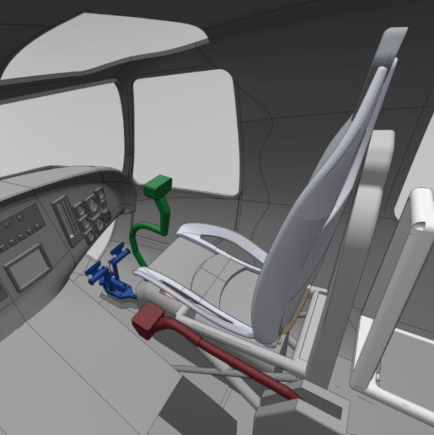
In the specific case of rotorcraft control, the most common inceptors arrangement involves both arms and legs and it is shown in Figure 1. The collective stick (shown in red) is operated by the left hand and can pivot so that the pilot can tilt it up or down in order to control the magnitude of the main rotor thrust; the cyclic stick (green) is operated by the right hand of the pilot to control the pitch and roll of the rotorcraft, by modifying the orientation of the main rotor thrust; lastly, the pedals (shown in blue), cause the rotorcraft to rotate about the vertical axis acting on the tail rotor thrust..
During the flight, possible adverse rotorcraft-pilot couplings (RPCs) may arise, and lead to incorrect inputs from the pilot. Consequently, wrong or, in general, unintended maneuvers could be performed. In rare cases, the result can lead to potentially catastrophic consequences. (Quaranta, Masarati, Lanz, Marforio, & Muscarello, 2014)
Figure 1. Typical inceptor layout
Human Systems Engineering and Design (IHSED 2021) https://openaccess.cms-conferences.org/#/publications/book/978-1-7923-8987-0
Enabling the investigation of the pilot hands activity n the control inceptors is thus an important area of research.
It is here underlined that, in addition to the reliability that would be required to such measurement systems, it is extremely important to avoid interfering with the pilot control action, also in terms of added workload.
RPCs PHENOMENA Even if human-machine interactions are present in many vehicle types, they are a significant factor in rotorcrafts, and they can in some cases lead to misleading cues. The reaction of the pilot to these cues can generate an unwanted behavior of the vehicle, possibly with unpredictable consequences. The misleading cues, coupled with an incorrect input from the pilot could therefore lead to other misleading cues resulting in an inadvertent feedback loop closure that might eventually have catastrophic consequences. (Pavel et al., 2013) (Pavel et al., 2011)
These kinds of events are usually generically referred to as Rotorcraft-Pilot Couplings (RPCs) and more specifically, regarding the example presented above, as PIO (Pilot Induced Oscillation): they involve the scenarios in which the pilot wrongly reacts voluntarily to misleading cues by acting on the inceptors. PIOs events generally occur in a frequency band up to 1 Hz.
Another type of RPC is known as PAO (Pilot Added Oscillation), in which an involuntary motion is induced to the pilot’s body and transmitted to the inceptors due to structural and aerodynamics vibrations: this kind of RPC, due to its nature, occurs in a frequency band between 2 and 8 Hz.
Higher frequencies are commonly filtered out by the biomechanics of the human body and are not relevant for RPCs investigation. (Muscarello, Quaranta, & Masarati, 2014)
OPT-IN SENSOR DESIGN AND CALIBRATION In the context of analysis and prevention of adverse rotorcraft-pilot couplings, gathering real-time information about the pilot action on the control inceptor can be of great importance. In this work, the design of a sensor able to measure the force exchanged between the pilot hand and the inceptor grip, without interfering with the piloting experience and without altering the ergonomic of the input device, is presented.
Human Systems Engineering and Design (IHSED 2021) https://openaccess.cms-conferences.org/#/publications/book/978-1-7923-8987-0
The sensor relies on a well-known optical working principle commonly referred to as frustrated total internal reflection (FTIR) (Zhu, Yu, Hawley, & Roy, 1986a). Such physical principle is already used in different fields of application (Castillo, Blanca, Cabrera, & Simón, 2006a). The prototype realization is based on existing preliminary studies (Lavatelli, Zanoni, Zappa, & Cigada, 2018a), that prove the feasibility of such an application.
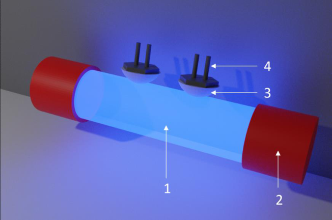
Looking at Figure 2, a transparent cylinder (1) is illuminated by two LEDs placed at the top and bottom facing to each other (2): the material of the cylinder is selected such that total reflection of the LEDs light is guaranteed. In the developed prototype, PMMA is used.
The individual force transducer is constituted by a hemispherical transparent elastic material (3), placed in front of a photoresistor (4). Force transducers are manufactured using silicon in the developed prototype.
When the hemispheric part is in contact with the cylinder, through the contact area the light reflected in the cylinder is frustrated, allowing it to be transmitted in the hemispheric probe: the photoresistor behind it will vary its resistance according to the amount of light passing through, which in turn depends on contact area between the hemispheric cell and the cylinder.
By measuring the voltage drop across the photoresistor, a quantitative measure of the luminosity in that point is given.
Figure 2. OPT-IN working principle
Human Systems Engineering and Design (IHSED 2021) https://openaccess.cms-conferences.org/#/publications/book/978-1-7923-8987-0
Since the area of contact varies with the pressure applied on top of the hemispherical part, there is a direct relation between the pressure exerted and the voltage drop across the photoresistor.
Two light sources are placed in the center of the stick’s grip: this allows to protect the cylindrical surface, that should remain clean in order not to change its local refraction coefficient. Furthermore, in this way, the light is not visible by the pilot.
The load cell is integrated in the handle as well: some small parts of the stick will be able to slide with respect to the rest of the stick itself, so that, when pressure is applied, they are free to sink by a small amount, which is almost unnoticeable by the pilot, but enough to cause a measurable change in contact area. The load cell, made of the photoresistor and the hemispherical elastic part, is placed below the movable part and in contact with the cylinder. The number of sensing element is limited only by the available space: note that more than one pressure cell can be connected to the central light source.
The size of the hemispherical elastic part, its material and the resistance of the photoresistor need to be selected according to the specific application and will strongly affect the sensibility and saturation value of the load cell. More than one photoresistor can be connected to one load cell to obtain a value which is averaged over the area of interest: in this case, they can be connected in series or read separately and averaged via software.
Two wires for each load cell are connected to a voltage reader, which will make the values available for any devices that will need this information in a range between 0 and 5 V. The acquired signal does not need any conditioning.
Human Systems Engineering and Design (IHSED 2021) https://openaccess.cms-conferences.org/#/publications/book/978-1-7923-8987-0
Figure 3. Cyclic prototype The final prototype is shown in the 3: it is a helicopter cyclic stick in which four OPT-IN sensors are included: two on the sides, one in front and the last one on the back. The positions are selected according to the common hand position of the pilot on the stick.
Figure available in the original PDF paper.
EXPERIMENTAL SETUP To the capability of the developed sensors, an experiment test has been performed on a desktop simulator. The experiment aims to monitor the right hand activity of the pilot on the cyclic stick of a helicopter during a flight containing different maneuvers. In particular, the workload for each maneuver will be evaluated in terms of the mean pressure exerted on the stick by the pilot as well as pressure variation in time.
The selected software for the experiment is FlightGear Flight Simulator 2020.3 whereas the cyclic stick is fixed to a flight stick joystick base which is used to control the helicopter during the simulated flight. The information about the X and Y inputs
Human Systems Engineering and Design (IHSED 2021) https://openaccess.cms-conferences.org/#/publications/book/978-1-7923-8987-0 from the joystick are detected during the flight using MATLAB Simulink. Data of the four sensors are collected directly by the Arduino UNO microcontroller and communicated via USB. The acquisition frequency of the OPT-IN sensors is 40 Hz, which is the maximum capability of real time USB communication allowed by the selected microcontroller, while the acquisition frequency of the joystick input is 10 Hz: this value is selected in order not to reduce the simulation framerate.
The post processing of the signals involves the synchronization of the signals coming from the two data acquisition systems and the resampling of the OPT-IN signals. It is performed in MATLAB with the following steps:
The beginning of the signals are removed in order to be synchronized with the joystick and the simulation using a cross-correlation after the resampling;
The mean of the pressure signals is removed in order to make it comparable with the joystick signal;
a Hampel filter is applied to remove outliers;
a fourth order median filter is applied to remove noise;
a minimum-order low-pass filter with a stopband attenuation of 60 dB is used, with a cut frequency of 10 Hz;
a saturation value is then selected according to the quantized saturation value of the photoresistor;
the signals are normalized with respect to the saturation value, in order to be comparable among each other and with the signals from the joystick.
The data from the joystick on the other hand, are already processed by the joystick control board so that they are already denoised and normalized when received. The same low pass filter applied to the sensor is used in order smooth out the steps caused by quantization.
The obtained signals from the OPT-IN sensors are combined in different ways in order to highlight different aspect of the flight workload:
Firstly, left and right sensor are subtracted from each other in order to compute the net pressure signal along the X direction and the same is done with the front and back sensors to obtain the same data along Y;
Also, in order to estimate the workload of the maneuvers, the sum of the signals along X and Y, the overall sum and the exerted pressure rate of change are computed in order to monitor the overall stress state and effort of the pilot.
Human Systems Engineering and Design (IHSED 2021) https://openaccess.cms-conferences.org/#/publications/book/978-1-7923-8987-0
The experiment consists in simulated flight which consists of two parts: firstly, the pilot is required to fly forward in a straight line, at a constant speed and altitude, after that, a precise hovering at low altitude is performed, during which the pilot is asked to maintain a target position and altitude as accurately as possible. Due to the different conditions experienced during the simulation, a different effort is expected by the pilot throughout the simulation (Zanoni et al., 2021a).
The two conditions are part of the same flight, which was performed in 225 seconds: 125 seconds for the cruise flight and 100 seconds for the precision hovering. The flight started from a hovering condition so that the pilot can avoid the challenging tasks involving the take-off.
RESULTS
After the flight is performed and the data are collected and filtered, the first result is the combination of the four OPT-IN sensors so that a comparison can be made with the signals from joystick: this is used to evaluate the consistency of the data from the sensors.
As shown in Figure 4, there is a strong correlation between the direction of the exerted pressure and the X and Y inputs from the joystick. Notice how spikes are corresponding throughout all the simulations and how the direction of the applied pressure is always coherent with the joystick input directions.
Given this first result, further investigations are performed by summing all the pressure values from the OPT-IN sensor. This information is used as an indication of the workload that the pilot is experiencing. As expected, an overall smaller pressure is exerted on the stick during the cruise flight, whereas greater pressure is detected in the most demanding maneuver phase.
The pressure variation during the simulation is shown in Figure 5, where the separation between the two flight phases occurs in correspondence of the red line.
Human Systems Engineering and Design (IHSED 2021) https://openaccess.cms-conferences.org/#/publications/book/978-1-7923-8987-0
Figure 4. X and Y signal from OPT-IN sensors and joystick base
Figure available in the original PDF paper.
Figure 5. Overall pressure in time
Figure available in the original PDF paper.
Human Systems Engineering and Design (IHSED 2021) https://openaccess.cms-conferences.org/#/publications/book/978-1-7923-8987-0
The result is quantitatively confirmed by the computation of the variance of the signal throughout the flight, as reported in the table below. The first six entries of the table show that there are no preferential directions in pilot activity, neither during the cruise part of the flight nor during the precision hovering. On the other hand, the last three entries prove that the variance of the signal during the cruise is smaller than the overall one, whereas it increases significantly during the precision hovering. This describes a remarkable rise in the effort of the pilot and a more demanding workload.
Table 1. Variances values Variance Value 𝜎𝑥 2 𝑡𝑜𝑡 0.0916
An innovative tool to detect and analyze the action of the helicopter pilot hands on the control inceptors has been presented. A pressure sensor based on the Frustrated Total Internal Reflection of light has been designed and several pressure cells have been embedded in a cyclic control stick of a desktop simulator. The capability of the sensor was proven in a flight simulation environment and metrics have been established in order to evaluate the workload and the effort required to the pilot during different maneuvers.
Future developments will focus on applying the sensors in an innovative approach to integrate the newly available data set, that will allow to further deepen the understanding of biomechanical couplings between pilots and rotorcraft, by collecting information about the hand activity on the control grip.
Human Systems Engineering and Design (IHSED 2021) https://openaccess.cms-conferences.org/#/publications/book/978-1-7923-8987-0
REFERENCES
Castillo, J., Blanca, A. P. D. L., Cabrera, J., & Simón, A. (2006). An optical tire contact pressure test bench. Vehicle System Dynamics, 44(3), 207–221. Hoh, R. H., Heffley, R. K., & Mitchell, D. G. (2006). Development of handling
qualities criteria for rotorcraft with externally slung loads. Lavatelli, A., Zanoni, A., Zappa, E., & Cigada, A. (2018). On the design of force sensors based on frustrated total internal reflection. IEEE Transactions on Instrumentation and Measurement, 68(10), 4065–4074. Muscarello, V., Quaranta, G., & Masarati, P. (2014). The role of rotor coning in
helicopter proneness to collective bounce. Aerospace Science and Technology, 36, 103–113. Muscarello, V., Quaranta, G., Masarati, P., Lu, L., Jones, M., & Jump, M. (2016).
Prediction and simulator verification of roll/lateral adverse aeroservoelastic rotorcraft–pilot couplings. Journal of Guidance, Control, and Dynamics, 39(1), 42–60. Pavel, M. D., Jump, M., Dang-Vu, B., Masarati, P., Gennaretti, M., Ionita, A., … others. (2013). Adverse rotorcraft pilot couplings—Past, present and future challenges. Progress in Aerospace Sciences, 62, 1–51. Pavel, M. D., Malecki, J., Dang Vu, B., Masarati, P., Gennaretti, M., Jump, M., …
Zaicek, L. (2011). Present and futur trends in rotorcraft pilot couplings (RPCs)-A retrospective survey of recent research activities within the European project ARISTO℡. Quaranta, G., Masarati, P., Lanz, M., Marforio, M., & Muscarello, V. (2014).
Biodynamic Adverse Rotorcraft-Pilot Coupling. 5th International Conference on Applied Human Factors and Ergonomics (AHFE 2014), 87–96. AHFE. Zanoni, A., Zago, M., Paolini, R., Quaranta, G., Galli, M., & Masarati, P. (2021).
On Task Dependence of Helicopter Pilot Biodynamic Feedthrough and Neuromuscular Admittance: An Experimental and Numerical Study. IEEE Transactions on Human-Machine Systems. Zhu, S., Yu, A., Hawley, D., & Roy, R. (1986). Frustrated total internal reflection: A demonstration and review. American Journal of Physics, 54(7), 601– 607.
Human Systems Engineering and Design (IHSED 2021) https://openaccess.cms-conferences.org/#/publications/book/978-1-7923-8987-0
LISTED IN THE AHFE DIGITAL BOOKSTORE CATALOGUE
Explore the complete digital volume
Human Systems Engineering and Design (IHSED2021): Future Trends and Applications
Read this individual research paper free through the original publisher, or explore the full digital proceedings book.
ISBN 978-1-7923-8987-0
Explore this ISBN in the AHFE Bookstore ↗Listed in the July 2026 bookstore catalogue; search by ISBN to confirm current availability · Digital book purchase optional