Giuseppe Quaranta, Pierangelo Masarati, Massimilano Lanz, Marco Marforio, Vincenzo Muscarelloa (2021). Biodynamic Adverse Rotorcraft-Pilot Coupling. In: Advances in Human Aspects of Transportation: Part I. AHFE Open Access, vol. 15. https://doi.org/10.54941/ahfe100607
This work discusses the dependence of helicopter aeroelastic stability on the pilot's biodynamic feedthrough. Two rotorcraft specific problems are presented. The modeling approach used in the investigation is briefly described, along with the experimental setup used for pilot biodynamic feedthrough characterization and for closed-loop problem investigation is described. The need to perform closed-loop experiments is discussed.
Pilots mainly interact with vehicles in a voluntary manner, producing actions on the control inceptors in order to perform the desired tasks. In some cases, the pilot can be deceived by erroneous or misleading cues, thus voluntarily producing control efforts that are erroneously phased with respect to the vehicle motion, resulting in undesired response. In such cases, phenomena initially called Pilot-Induced Oscillations (PIO) may occur.
In other cases, the pilot may involuntarily produce control efforts as a consequence of vibrations of the cockpit, producing what have been termed Pilot-Assisted Oscillations (PAO). Specific attention is dedicated to such involuntary interaction between the vehicle and the pilot. This phenomenon is often called biodynamic feedthrough, namely the feeding of commands into the control inceptors that are the involuntary consequence of external disturbances caused for example by vibrations of the vehicle. Such commands may further excite the dynamics of the vehicle, causing a degradation of the flight dynamics qualities, difficulties in achieving the desired performance, and ultimately produce an unstable closure of the control loop.
The problem may affect all kinds of vehicles whose pilot is accommodated within the vehicle and thus is subjected to its motion. In this work, it is addressed by identifying the appropriate modeling requirements for all the components involved in the process: the aeromechanics of the vehicle and its components, the dynamics of the control system and, specifically, the biomechanics of the pilot. Modeling and analysis tools are developed, including detailed multibody dynamics and linearized analysis formulations for both the vehicle and the pilot. Typical adverse couplings are investigated and discussed, with reference to numerical models of representative vehicles interacting with pilot models resulting from identification.
This work discusses classical helicopter aeroelastic RPC events: the collective bounce and the lead-lag/roll instability. Collective bounce is the consequence of an adverse interaction of the pilot with the vertical motion of the helicopter, in which the highly damped main rotor coning mode plays an essential role by introducing enough phase delay in the vertical acceleration of the vehicle in response to collective control input to reduce the phase margin of the vehicle when the collective control loop is closed by the involuntary pilot's response to the vertical acceleration of the seat. Lead-lag/roll instability is caused by the interaction of the regressive lead-lag motion of the main rotor blades, which cause a dynamic unbalance of the rotor that interacts with the motion of the vehicle about the roll axis. Such motion, in turn, causes an involuntary action of the pilot on the lateral cyclic control, which unintentionally closes the control loop. It is shown, both numerically and experimentally, that for specific vehicle configurations some pilots, based on their biodynamic feedthrough, may drive the closed loop system unstable.
Those problems have been investigated also experimentally in the flight simulator, with professional test pilots controlling the numerical models of the helicopters through specially crafted mission task elements. In particular it has been possible to investigate how the biodynamic feedthrough changes while the pilot is performing different Mission Task Elements (MTE), showing that there is a correlation between the pilot workload and the biodynamic feedthrough.
The modeling approaches are briefly recalled, along with the experimental setup used to investigate the problem. The dependence of the pilots' biodynamic feedthrough transfer functions on the task is discussed. Specifically, it is shown how the closure of the involuntary control loop affects the pilot's transfer functions, motivating the need to conduct specific experiments in closed loop configuration.
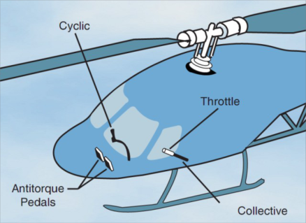
ANALYSIS OF ROTORCRAFT-PILOT COUPLINGS PROBLEMS Helicopters are controlled by pilots using control inceptors whose layout evolved into a standard configuration, with few notable exceptions. Figure 1 illustrates a typical layout.
Figure 1. Typical helicopter control inceptors arrangement (from Anonymous, 2000).
A central stick, analogous to that of many fixed-wing aircraft, is usually held using the right hand. The center stick can be moved fore and aft and sideways. Such commands are transduced into appropriate motion of a mechanical component, called the “swashplate”, which in turn induces the periodic pitching of the rotor blades, thus causing periodic changes in blade loads that make the main rotor disk tilt. The tilting of the disk ultimately changes the direction of the thrust, thus producing control moments about an arbitrary axis orthogonal to the axis of rotation of the rotor. Control moments about the pitch and the roll axis are respectively obtained by moving the stick fore-aft and sideways. The role of this control is essentially analogous to that of the alternative arrangements of center stick, side stick or wheel that are in use in conventional fixed-wing aircraft.
Another control, specific of helicopters, is the so-called collective control inceptor, which operated by the pilot using the left hand. Such control produces a collective change of the pitch of the main rotor blades, thus controlling the amount of thrust the rotor generates. A change in thrust is usually accompanied by a change in torque required to keep the rotor angular velocity at the desired value, so the collective control inceptor used to incorporate a throttle Human Aspects of Transportation I (2021) control, much like the throttle of a motorbike. Modern helicopters use an automatic control system, called FADEC, that acts on the fuel flow to keep the angular velocity of the rotor as close as possible to the nominal value regardless of the collective requested by the pilot.
Finally, pedals are used to control the collective pitch of the tail rotor, producing a moment about the yaw axis. This control is analogous to the deflection of the rudder in fixed-wing aircraft.
When the pilot is subjected to accelerations, involuntary control actions can be inserted into the flight control system. Indeed, accelerations are transmitted from the seat to the pilot's shoulders. The suspended mass of the pilot's arms is also subjected to inertia forces. This phenomenon is often called biodynamic feedthrough (BDFT). BDFT in general may produce annoying disturbances, increased vibratory level and discomfort; it may increase the workload of the pilot, for example because it disturbs the vision of the displays, or because it requires more attention of the pilot to perform the required task. The problem becomes more critical when there is a direct relationship between the direction of the accelerations that affect the pilot and the control forces and moments produced by a motion of the controls caused by such accelerations. In those cases, the stability of the closed loop pilot-vehicle system (PVS) may be jeopardized.
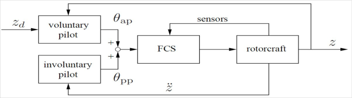
As shown in Fig. 2, from a topological point of view voluntary and involuntary controls may be interpreted as two independent feedback control loops (although the problem may be more complex). Voluntary control action stems from the perception of the vehicle behavior, which is acquired by the pilot using several sensors: visual, inertial (accelerations), proprioceptive just to mention the main ones. The cognitive level of processing of such information and, to some extent, the reflexive level, produce voluntary (and sometimes reflexive) actions on the control inceptors. As anticipated, BDFT (that is the direct, mechanical effect of vibrations on the pilot's limbs) produces additional, involuntary control inputs that are added to the voluntary ones. Their combination produces the actual motion that is commanded by the control inceptor to the control system.
Figure 2. Feedback loops between vehicle and pilot.
The phenomena involved in helicopter BDFT present several peculiarities and require some careful study to point out the root causes. Understanding the phenomenon is essential to support the design of vehicles and human- machine interfaces (HMI) that mitigate its insurgence.
In this work, the analysis involves the detailed modeling of the pilot, of the vehicle and of their interaction. Such analysis is important to understand what factors play an important role, and to define the modeling requirements for an appropriate analysis, in support of the design of new vehicles and HMIs. Pilot models have been developed according to two distinct approaches.
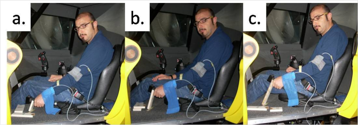
1. Linear, frequency domain models have been obtained by identifying the results of BDFT experiments (Fig. 3). The experiments involved human subjects sitting in a flight simulator pod and holding the control inceptors (see for example Masarati, Quaranta and Jump, 2013). Most of the experiments involved in this work were performed at the flight simulation laboratory of the University of Liverpool (UoL), within the joint research efforts mentioned earlier. The cooperation and the support of UoL, especially in the person of Dr. Michael Jump, is here duly acknowledged.
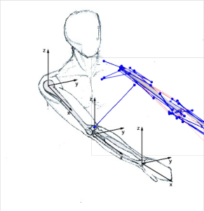
2. Detailed numerical models of the pilot have been developed within a general-purpose multibody dynamics environment (Fig. 4), based on biomechanical data available from the open literature (see for example Masarati, Quaranta and Zanoni, 2013). Those models have been either directly used in “monolithic” multibody simulations of the coupled PVS, or used to produce numerical experiments and synthesize transfer functions to be used in linearized analysis, much like the models obtained directly from experiments.
It is worth stressing that the capability to produce linearized models of the pilot's involuntary behavior from numerical analysis paves the way for predicting BDFT within yet untested HMI configurations and cockpit layouts.
Figure 3. Biodynamic feedthrough experimental setup for collective control inceptor.Figure 4. Pilot arm detailed multibody model.
Experiments were also used to verify the predicted adverse interaction between the pilot and the vehicle. The two problems of vertical bounce and roll were considered using rather different approaches. In fact, in the case of vertical bounce, a purely biomechanical adverse interaction is postulated, when appropriate system parameters are considered, whereas in the case of roll axis instability it can only occur when the pilot is required to perform a high- gain task.
VERTICAL BOUNCE One may speculate that the minimal vehicle model capable of describing the problem is a rigid-body model. In such case, the motion of the helicopter along the vertical axis is all one needs to describe the vehicle. In this case, one can easily show that no instability is possible within realistic vehicle parameters when using realistic models of the pilot BDFT.
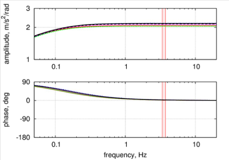
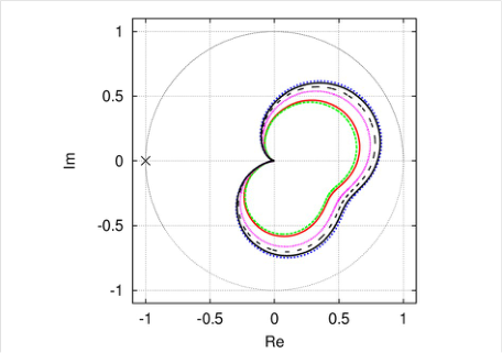
Figure 5 (left) shows that helicopter types that significantly differ in size and characteristics of the main rotor system present a nearly identical behavior in terms of vertical acceleration resulting from collective control input when the main rotor coning motion is neglected. Figure 6 (left) shows that the corresponding Loop Transfer Function (LTF), obtained by closing the feedback loop with a realistic involuntary pilot model (the one identified in (Mayo, 1989), characterized by two complex conjugated poles at about 3.5 Hz with about 30% damping), is not going to circle around point (-1), thus always complying with Nyquist's stability criterion no matter of how much the feedback gain is increased. In this context, the feedback gain can be interpreted as the ratio between the rotation of the collective control inceptor and the actual pitch rotation of the main rotor blades. A realistic nominal value is considered in the curves, leading to stable and reasonably behaving curves for all the helicopters considered in the plots.
Figure 5. Vertical acceleration as a function of collective control (left: without, and right: with rotor coning).Figure 6. Loop transfer function of involuntary collective control (left: without, and right: with rotor coning).
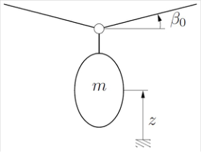
On the contrary, when the main rotor coning mode (Fig. 7) is considered, a rather different behavior can be observed. Figure 5 (right) shows some amplification for some helicopters, and none for others; all vehicles show significant phase lag in the vicinity of the frequencies of the pilot model's poles. The corresponding LTF (Fig. 6, right) now crosses the negative imaginary axis; as a consequence, an increase of feedback gain could lead to loss of stability.
Figure 7. Rigid-body heave and main rotor coning model.
It is worth stressing that pilots often prefer high feedback gain for several reasons: high gain means that the same amount of thrust change can be obtained with a smaller motion of the controls. As a consequence, the whole range of blade pitch can be obtained with less overall motion of the hand, which can be held about the most comfortable position for most of the time. Moreover, high gain is felt as a more prompt response to control inputs. Pilots can easily adjust themselves to gain changes (and in general to response changes) thanks to training (the response can be somehow predicted by the pilot as long as it conforms with the mental model the pilot has of the vehicle) and to adaptation that is intrinsic in humans when acting as regulators of predictable processes. As a consequence, from the point of view of voluntary control, a request for change of feedback gain is perfectly legitimate and, within reasonable bounds, compatible with the behavior of human operators. However, as shown by this simple analysis, a change of feedback gain changes the involuntary contribution to the control input and can lead to loss of stability.
Experiments performed in the flight simulator considering a closed-loop setup, in which the force applied to the analytical model of the vehicle were determined by the motion of the control inceptor, showed a loss of stability of the coupled PVS as the feedback gain was increased (Masarati, Quaranta, Lu and Jump, 2014). In that case, engineer (i.e. nonprofessional) pilots as well as one professional test pilot were considered in the experiment. Experiments were performed considering a simple, 2 degree of freedom model that describes the motion of the vehicle along the vertical axis (in analogy with the model of Fig. 7) with an additional degree of freedom that was tuned to produce some desired dynamics (not necessarily those of rotor coning). The dynamics associated with this second mode were used to produce the desired characteristic frequency and damping, to investigate the interaction of the involuntary pilot with specific vehicle dynamics.
The results highlight several interesting aspects:
1. the insurgence of the instability is very subjective, both inter-subject and intra-subject; different tests yielded different stability and post-stability threshold of the feedback gain, although common trends appeared;
2. the instability is dominated by the biodynamic characteristics of the pilot; this was assessed by modifying (specifically by detuning the structural dynamics from their nominal value) and noticing that the frequency of the instability is characterized by a frequency close to that of the pilot;
3. no pilot was RPC-free; pilots that reached instability with some vehicle configuration did not reach instability with other configurations, and vice versa;
4. closed-loop experiments clearly (although indirectly) show an adaptation of the voluntary behavior of the pilot to changes in the feedback gain, as expected, but also a dependence of the involuntary behavior. This dependence is somehow subtle, and the type and amount of tests performed did not allow to fully understand it, but it is clear that as the instability is approached, the voluntary behavior of the pilot changes (the pilot acts more cautiously); this has an impact on the involuntary dynamics, reducing the proneness to RPC. It is conjectured that by acting more cautiously, the pilot actually modifies the biomechanical properties of the limbs, reducing their equivalent stiffness, and thus decoupling the biomechanical poles from those of the vehicle. This aspect needs further analysis to be adequately quantified.
ROLL-AXIS INSTABILITY Roll axis dynamics has been prone to adverse pilot-vehicle interaction. In fixed-wing aircraft the source of adverse interaction has been often identified either in the flexibility of the vehicle (e.g. low frequency skew-symmetric wing bending that interacts with rigid-body roll dynamics to yield sufficient phase delay in the roll response) or other sources of delay (e.g. input processing by a digital flight control system, or insufficient bandwidth or saturation of control system actuators).
In helicopters, a possible source of adverse interaction is associated with the lead-lag motion of the main rotor blades. Specific combinations of blade lead-lag motion displace the center of mass of the rotor from the axis of rotation. Those combinations are known as `progressive' and `regressive' lead-lag modes. When such motions occur, the center of mass of the rotor moves along a trajectory that precesses about the rotation axis either in the same direction (the progressive mode) or in opposite direction (the regressive mode). Such dynamics are damped by lead-lag dampers that are usually present to prevent such dynamics from coupling with pitch and roll of the vehicle when standing on the landing gear. The corresponding dynamic phenomenon is well-known as `ground resonance'. A similar phenomenon may occur, when the helicopter is airborne, as long as the roll motion is controlled by some form of feedback that reacts to roll motion with a cyclic change of blade pitch that produces a counteracting control moment of the main rotor. Such phenomenon is known as `air-resonance' when the feedback loop is closed by a Stability (and Control) Augmentation System (S(C)AS). However, the pilot himself may close such control loop through the involuntary interaction with the vehicle dynamics. This phenomenon requires some specific circumstances to appear:
1. acceleration about the roll axis must produce an involuntary control input
2. the regressive lead-lag motion must have low damping; this is usually the case in helicopters that do not suffer from ground resonance, and thus have little if any blade lead-lag damping
3. lead-lag motion must be sufficiently coupled with roll; this is usually the case, since the main rotor is well offset vertically from the roll axis
4. the lead-lag regressive mode, in the non-rotating frame, must be in the vicinity of the pilot's biomechanical modes; typical figures for the latter, according to the open literature and to experiments performed within the present work, are between 1 Hz and 2.5 Hz.
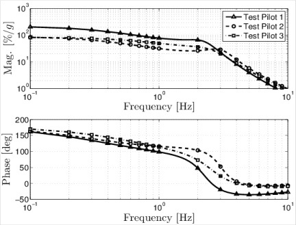
Figure 8 presents the pilot BDFT related to lateral cyclic control input as a function of lateral acceleration for three professional helicopter test pilots as measured during a dedicated test campaign performed during the project ARISTOTEL (Muscarello, Masarati, Quaranta, Lu, Jump and Jones, 2013).
Figure 8. Pilot BDFT for lateral cyclic control as a function of lateral acceleration.
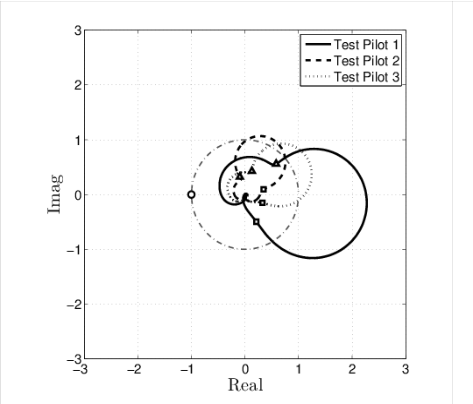
The figure clearly shows significant differences between the three pilots, which are explained partly by their attitude towards aircraft control, and partly by their build (pilot 1 was significantly taller than the other two). Notice how pilot 1 shows a significant occurrence of phase delay at about 2 Hz, whereas the other two pilots show a comparable amount of delay at higher frequency, together with less pronounced amplification. The combination of these two factors, the phase delay and the amplification at about 2 Hz, produces the Nyquist plots of the LTFs shown in Fig. 9. Figure 9 (left) shows the LTF of the three pilots for a helicopter with hingeless main rotor (5% damping of the regressive lead-lag mode). The helicopter is modeled using a linear state space model that includes essential airframe and main rotor dynamics (all rigid-body and several aeroelastic modes well above the bandwidth of the pilot; control system actuator dynamics, SCAS). The exercise of reducing the model to the minimum number of states that still describe the phenomenon has not been tried yet.
The three pilots show a rather different behavior. The feedback gain is 2.5 the nominal value, a value that does not prevent the pilots from performing several high-gain tasks, but makes the vehicle oversensitive. Figure 9 (right) shows the same plots with 140 ms of digital time delay between the lateral cyclic control input and the actual blade pitch change. As one can clearly appreciate, now pilot 1 is at the verge of instability, because the time delay basically `rotates' clockwise the curve of Fig. 9 (left), without impacting the magnitude.
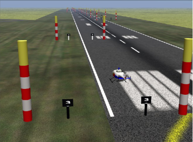
Figure 9. LTF of roll for a hingeless helicopter in forward flight, 80 kts (left: no; right: 140 ms time delay) An instability of this type only appears when the pilot triggers it by performing some specific task. In fact, usually cyclic lead-lag motion, being at least slightly damped, is not present unless triggered by specific abrupt maneuvers, like those about the pitch and the roll axes. The results of this simple analysis have been assessed by performing a dedicated test campaign in the flight simulator. The test pilots were requested to fly a `roll step' maneuver (Fig. 10), i.e. to fly along the left edge of a runway, perform a sharp right turn to line up with the right edge, fly straight a little bit more, and then return on the left edge with a sharp left turn. The sharp turns are intended to excite the rotor dynamics, significantly the lowly damped regressive lead-lag mode.Figure 10. Roll step maneuver course layout.
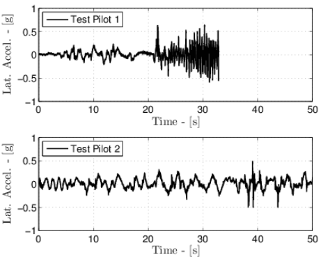
Indeed, it was shown by the experimental results (Fig. 11) that pilot 1 was able to incur into a Limit Cycle Oscillation (LCO) for a feedback gain of 3 times the nominal and a time delay of 100 ms (i.e. similar to those of Fig. 9 (right)). The oscillation was repeatable, at about 2.2 Hz, which is the frequency of the regressive lead-lag mode. Inspection of the state of the helicopter aeromechanics model implemented in the flight simulator confirmed that the LCO was associated with the regressive lead-lag mode.
Figure 11. Lateral acceleration (left) and lateral cyclic stick deflection for pilots 1 & 2 at feedback gain 3 times nominal and 100 ms time delay between control input and actual blade pitch rotation.
Figure 11 shows that pilot 1 had to abort the task shortly after lining up after the first roll step. Such a repeatable pattern seems to indicate that the pilot could manage to fly the helicopter as long as the regressive lead-lag mode was not yet excited; he was also able to fly the helicopter throughout the roll step itself (i.e. the roll maneuver initiation and completion, which is essentially based on anticipating the response of the vehicle to compensate for the high time delay, and thus is essentially a feedforward maneuver), but failed to perform the subsequent “capture” phase, that is required to level the helicopter with respect to the roll axis. Such maneuver is a high-gain tracking task (essentially a feedback task), which requires firm pilot action; the pilot involuntarily “stiffens” while performing high-gain tracking, and thus increases the feedback gain of the involuntary response LTR, driving the coupled system unstable. The instability immediately reveals itself because the just performed roll step maneuver excited the regressive lead-lag mode. Thus, the combination of the maneuver, which excites the mode, and the stiffening of the pilot, which moves from a “pursuit” (i.e. feedforward) to a tracking (i.e. regulatory feedback) task, act as triggers of the instability.
As a further check, a similar aeromechanics model, with the regressive lead-lag mode switched off, could be flown in the same configuration, safely bringing the task to completion. Curiously enough, pilot 2, who did not incur in LCOs with the model that included the regressive lead-lag as predicted in Fig. 9 (right), did incur into “conventional” rigid-body PIO associated with flight mechanics (i.e. rigid-body roll).
CONCLUSIONS
Adverse aeroelastic rotorcraft-pilot couplings may jeopardize the stability of helicopters in specific operating conditions. This work describes recent research activities aimed at understanding specific problems, determining the modeling requirements for their analysis and investigating them both numerically and experimentally. The vertical bounce and roll axis problems are analyzed. The vertical bounce involves the vertical motion of the helicopter and the collective control inceptor, which is held by the pilot's left hand. It is discussed how the main rotor coning motion plays a fundamental role by introducing phase delay between the control action and the vertical acceleration of the vehicle at the frequencies that characterize the involuntary action of the pilot. The roll axis instability involves helicopter roll and lateral displacement and the lateral cyclic control, which is held by the pilot's right hand. It is discussed how the main rotor regressive lead-lag motion plays an essential role by introducing a lowly damped mode in the band of frequency that is characteristic of the involuntary action of the pilot. Although outside the scope of this work, alleviation of the phenomena can hardly be obtained by modifications to the aeromechanics of the vehicle, since they are the result of performance optimization. Typical means involve modifications of the dynamics of the control system, including modifications to the control inceptors and digital filtering for augmented and fly-by-wire vehicles.
REFERENCES
Anonymous (2000), “Rotorcraft Flying Handbook”, FAA H-8083-21, Federal Aviation Administration. Masarati, P., Quaranta. G., Jump, M. (2013), “Experimental and numerical helicopter pilot characterization for aeroelastic rotorcraft-pilot couplings analysis”, Proc. ImechE, Part G: J. Aerospace Engineering, vol. 227, no. 1, pp. 124-140, doi:10.1177/0954410011427662. Masarati, P., Quaranta, G., Zanoni, A. (2013): “Dependence of helicopter pilots’ biodynamic feedthrough on upper limbs’
muscular activation patterns”, Proc. IMechE Part K: J. Multi-body Dynamics, vol. 227, no. 4, pp. 344-362, doi:10.1177/1464419313490680. Masarati, P., Quaranta, G., Lu, L., Jump, M. (2014): “A closed loop experiment of collective bounce aeroelastic rotorcraft-pilot coupling”, Journal of Sound and Vibration, vol. 333, n. 1, pp. 307-325, doi:10.1016/j.jsv.2013.09.020. Mayo, J. R. (1989), “The involuntary participation of a human pilot in a helicopter collective control loop”, in: 15th European
Rotorcraft Forum, pages 81.1-12, Amsterdam, The Netherlands, 12-15 September 1989. Muscarello, V., Masarati, P., Quaranta, G., Lu, L., Jump, M., Jones, M. (2013) “Investigation of adverse aeroelastic rotorcraftpilot coupling using real-time simulation”, in American Helicopter Society 69th Annual Forum, Phoenix, Arizona, May 21- 23 2013. Paper No. 193.
LISTED IN THE AHFE DIGITAL BOOKSTORE CATALOGUE
Explore the complete digital volume
Advances in Human Aspects of Transportation: Part I
Read this individual research paper free through the original publisher, or explore the full digital proceedings book.
ISBN 978-1-4951-2097-8
Explore this ISBN in the AHFE Bookstore ↗Listed in the July 2026 bookstore catalogue; search by ISBN to confirm current availability · Digital book purchase optional