Zachary Guyton, Kristina Kuhlken, Michael Lowe (2025). Task Analysis: A Model Based Human Systems Engineering Approach. In: Creativity, Innovation and Entrepreneurship. AHFE Open Access, vol. 166, pp. 10–19. https://doi.org/10.54941/ahfe1006105
Model-Based Systems Engineering (MBSE) is the formalized application of modeling to support system requirements, design, analysis, verification, and validation activities beginning in the conceptual design phase and continuing throughout development and later life cycle phases. Human Systems Engineering (HSE) consists of human factors engineering, safety, training, survivability and force protection, habitability, manpower, personnel, training, and human-centered engineering. Model-Based Human Systems Engineering (MBHSE) is the intersection of the two disciplines. MBHSE aims to address the deficiencies of MBSE in adequately including humans within system and analytical models. A key pillar of effective Human Systems Engineering is the Critical Task Analysis. A Critical Task Analysis (CTA) is a systematic process used to identify, analyze, and evaluate critical tasks within a system or process. These are tasks that, if not performed correctly, can have significant negative consequences such as accidents, injuries, system failures, or financial losses. One comprehensive CTA approach is through a Mission Task Analysis (MTA). An MTA systematically analyzes how operators interact with the system within the context of specific mission goals and operational environments. MTA is a method of task analysis designed to cover all aspects of the mission under all expected operating and environmental conditions. Conceptually, MTA operates on three levels. At the mission level, the goal is to identify system requirements that map to human performance requirements. At the function level, the method allocates functions and identifies machine-related requirements that translate into human performance requirements. At the task level, the method identifies specific behaviors, information flows and needs, interaction dynamics, decision parameters, safety assessments, workload dynamics (visual, auditory, cognitive, and psychomotor), automation considerations, and other key human factors elements.Current MBSE methods, practices, standards, and procedures omit key elements of how operators interact with systems-of-interest. This paper describes a novel approach to effectively model system operators and users. The MBHSE task analysis outlined in this paper uses SysML to conduct and capture a Mission Task Analysis in support of system design and improvement. The approach focuses on both compiling existing MBSE architecture models and generating new models that provide more information about critical tasks. Existing views that support a task analysis include the Department of Defense Architecture Framework (DODAF) Operational Activity to Systems Function Traceability Matrix (System View 5a; SV-5a), Operational Activity to Systems Traceability Matrix (System View 5b; SV-5b), Operational Activity Decomposition Tree (Operational View 5a; OV-5a), and Operational Activity Model (Operational View 5b; OV-5b). Relying solely on these existing views does not allow human systems engineers to fully conduct, represent, or communicate the requisite components of a Critical Task Analysis.To augment standard MBSE approaches, MBHSE generates additional models. These include models that show task-relevant information exchanges within the system architecture; models that capture all variations of the sub-tasks steps and sequences; models that capture the key input and output parameters for decisions related to the critical tasks; models that provide design recommendations for various levels of automation relating to a task; and models that capture the critical knowledge, skills, and attributes (KSAs) operators must possess to execute a task.
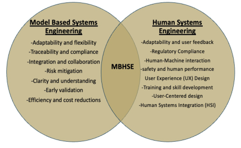
Model-Based Systems Engineering (MBSE) is the formalized application of modeling to support system requirements, design, analysis, verification, and validation activities beginning in the conceptual design phase and continuing throughout development and later life cycle phases (INCOSE, 2007). Human Systems Engineering (HSE) encompasses various elements, including human factors engineering (cognitive workload, ergonomics), safety (hazard analysis, risk mitigation), training (skill development, knowledge transfer), survivability and force protection, habitability, manpower, personnel, and human centered engineering. Traditional MBSE can overlook how operators interact with complex systems, which can lead to designs that are inefficient, unsafe, or difficult to use. MBHSE is the intersection of the two disciplines (Figure 1). MBHSE aims to address the shortfalls of MBSE to adequately include humans.
Model Based Mission Task Analysis Mission Task Analysis (MTA) systematically analyzes how operators interact with systems within the context of specific mission goals and operational environments. It provides a structured approach to understanding human
Task Analysis: A Model Based Human Systems Engineering Approach 11
performance requirements and identifying potential design issues. MTAs have proven successful in a number of previous programs across the DOD.
Figure 1: Model based human systems engineering.
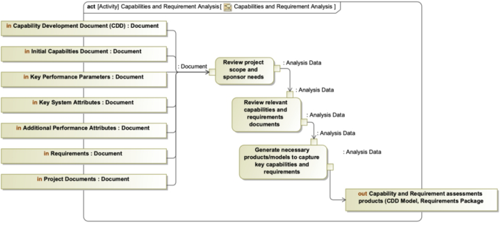
Conceptually, MTA operates on three levels, missions, functions, and tasks. At the level of missions, the goal is to identify system requirements that map to human performance requirements. At the level of functions, the goal is to identify and decompose system functions and allocate functions to the operator or the system. At the task level, the goal is to identify specific behaviors, information needs, interaction dynamics and task performance statistics that are needed to assess conformance with requirements and specifications, estimate workload, and Evaluate potential errors. The MTA starts with a thorough assessment of key capability and requirement documents (Figure 2).
Figure 2: Mission task analysis inputs.
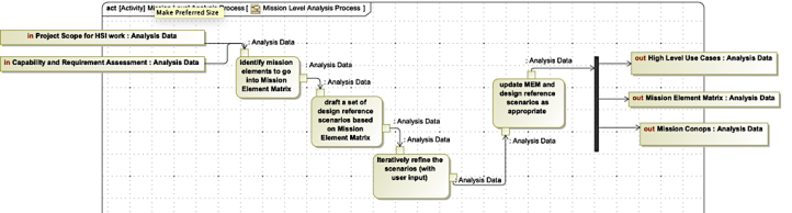
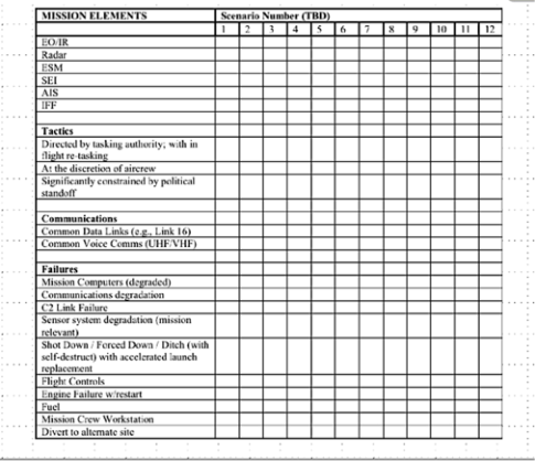
Mission Level Analysis The primary activity in conducting a mission level analysis is the development of reference scenarios and CONOPs that define the operational context that drives the sequence of user actions and system functions required to achieve mission objectives and sub-objectives. The inputs to the mission level analysis are capability documents, requirement documents, and other appropriate programmatic documents; the outputs are use cases, a Mission Element Matrix (MEM), and design references scenarios or CONOPS (Figure 3). The mission element matrix contains “mission elements” in the rows and references scenarios or CONOPs identifiers in the columns. The MEM defines which mission elements are contained in each scenario and helps ensure full coverage of all mission elements in the analysis (Figure 4).
The design reference scenarios and CONOPs should focus on frequent scenarios, scenarios that significantly stress users or the system, scenarios that significantly impact mission outcomes, failure and exception scenarios, scenarios that include critical functions, scenarios that include new functions,
Task Analysis: A Model Based Human Systems Engineering Approach 13
and scenarios that include interactions-of-interest between the user, the system, or external systems (Friedenthal et al., 2014). The reference scenarios will illustrate requirements and capabilities across a broad range of mission elements that include a variety of performance, environmental, mission, and operational conditions. Following the mission level analysis, the function level analysis is completed.
Mission Task Analysis Model The mission task analysis model uses structural (e.g., blocks), strategic (e.g., UAF capabilities), or other appropriate model elements to represent mission elements and reference scenarios. These elements are then traced to capabilities and requirement documents, requirements, and other task analysis outputs. This provides comprehensive traceability of individual task analysis elements to high-level tactical, operational, and strategic level capabilities, requirements, and other items of interest.
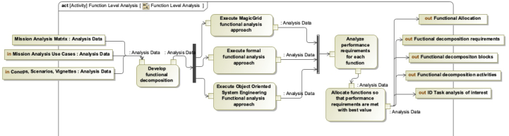
Function Level Analysis The function level analysis examines the system at the next lower level. The functions are analyzed and operator roles in each function are defined. The inputs to this process are the mission elements, design reference scenarios, and CONOPs; the outputs are a functional analysis and definition, functional decomposition, and functional allocation (Figure 5). The first step in the function analysis is the generation of a list of functions. Sub-functions are identified for each higher-level functional breakout element. Each function is identified and defined operationally. Operational definitions provide consistency, reduce ambiguity and overlap, and are necessary preparations for subsequent operator task analysis activities.
Figure 5: Function level analysis process.
Function allocation is the assignment of the defined system functions. Functions are allocated to software, operators, automation/AI, or to a combination of all three. The process of designating who (i.e., operator) or what (i.e., software or hardware) will perform a given function is a critical engineering activity. On modern systems, allocation of a given function is often dynamic. The function analysis identifies when an allocation should be dynamic in order to achieve an operational goal and identifies the necessary conditions that would allow the system to reallocate the function dynamically, and then return to default allocation states. For example, in
an optionally piloted vehicle, the function “maintain situational awareness” could be dynamically allocated between the human pilot and an AI-powered sensor fusion system, depending on factors like visibility, pilot workload, and threat level.
During any function allocation process, designers must have access to a reliable approach for assigning an appropriate level of automation. The most appropriate roles for human and software/hardware components must be determined. A combination of approaches and perspectives are used to categorize autonomous functions: (a) dependency and authority – which agent/operator assumes the lead and which is in support for a specific task (Guyton et al., 2022); (b) information processing implications – this may include variable assignments of different levels of automation to specific functions and states; (c) situational awareness levels – the ability to perceive, understand, and project elements of the operational environment within a given time and space; and; (d) distinctive roles and function characteristics, which dynamically assess roles across goals, intentions, actions, perception, and analysis (O’Neill et al., 2022).
Function Level Analysis Model The function task analysis model uses activities, activity diagrams, state machine diagrams, block definition diagrams, and traceability matrices to capture the structure, behavior, operational states and modes, and allocation of system functions. There are conventional techniques such as MagicGrid (Aleksandraviciene & Morkevicius, 2021), Object Oriented Systems Engineering Method (INCOSE, 2023; Friedenthal et al., 2014) or other well established systems engineering approaches that can be leveraged to conduct the function level analysis within the MBSE tool.
Task Level Analysis Following the function level analysis, the task analysis is performed for all functions allocated to human operators and automation. These tasks are analyzed in the context of the system functions the they interact with. The task analysis identifies and describes operator or maintainer tasks associated with each function, with emphasis on tasks related to system operations. Often the list of tasks can be derived directly for the function analysis by adding operator tasks to each lowest-level function. The descriptive component of the task analysis consists of a brief description of operator activities required to perform each specific task.
Table 1: Task analysis categories of interest for identified tasks.
Table available in the original PDF paper.
1 General Mission Function List 1 General Mission function criticality (Mission specific) 1 General Decision(s) required to accomplish mission function(s) 2 Information Information presented (by SS/component) 2 Information Information/Cues that initiate mission functions 2 Information Method to gather information required for task 2 Information Type of information that is gathered Continued
Task Analysis: A Model Based Human Systems Engineering Approach 15
Table 1: Continued
Table available in the original PDF paper.
Information processing (IP): Workload VCAP
2 Information Information available to user 2 Information L1 Information requirements (data) 2 Information L2 Information requirements (understanding) 2 Information L3 Information requirements (prediction) 2 Information Difference between required/available information 2 Information Modality information is conveyed 3 Information processing IP: Decision Evaluation Process
3 Information processing
4 Task performance
Performance consequences of each task to SSS, overall system, and mission 5 Decision Possible Decisions that could be reached 5 Decision Responses to information/cues and combinations of information and cues 5 Decision Self-initiated Responses 5 Decision Cues that support decision logic 6 Workspace Workspace envelop required for all possible actions 6 Workspace Workspace available 6 Workspace Location of user within the workspace with relation to task interfaces 6 Workspace Location/condition of work environment 7 Actions All possible actions 7 Actions Frequency 7 Actions Tolerance/acceptable values (performance) 7 Actions Feedback 7 Actions Tools/equipment required 7 Actions Concurrent tasks and associated workloads/attentional considerations. 7 Actions Impact of operating and maintaining equipment with PPE 7 Actions Modality of action to system 7 Actions Body Movements required to execute task 8 Personnel # personnel required 8 Personnel Personnel KSAOs, ranks, ratings, etc. 8 Personnel Job aids, training, references required and their timely availability (also action) 8 Personnel Personnel interactions where more than one person is involved 8 Personnel Performance limits of personnel 8 Personnel Sense modalities required 9 Error Consequences and severity of human error 9 Error Potential for error recovery 9 Error Errors of omission 9 Error Errors of commission 10 Communication Communications required 10 Communication Type of communication 11 Safety Hazards involved 11 Safety Other Safety items of interest 12 System Operational limits of hardware/software and associated user interfaces Continued
Table 1: Continued 13 Automation Levels of automation 13 Automation Stages of automation 13 Automation Automation candidate functions 13 Automation Automation TRLs and HRL compatibility and projections 13 Automation Data required to support levels of Automation for various L3 info requirements 14 Other HCI principles/Guidelines 14 HMI HMI required 14 HMI HMI Available 14 HMI HMI Ideal 14 HMI Control Needs 14 HMI Display Needs 15 Other HCI principles/Guidelines
Table available in the original PDF paper.
There are various categories of interest related to each task can be investigated depending on the specific research questions of interest (Table 1). Categories include goals, information parameters, information processing parameters, decision parameters, workspace parameters, action parameters, personnel parameters, communication parameters, system parameters, HMI parameters, and automation parameters.
Information requirements are identified for each task. From the static task analysis, we can identify nominal requirements (i.e., statements about what the operator is expected to do). From the design reference scenarios, qualitative (i.e., as least enough for a reference) and quantitative (i.e., with some specified degree of accuracy or precision, or within some defined time period, or above or below some specified threshold) performance requirements are defined. Interviews and stakeholder discussions with experienced personnel may lead to documentation of further information requirements that can be incorporated into the design.
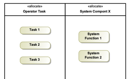
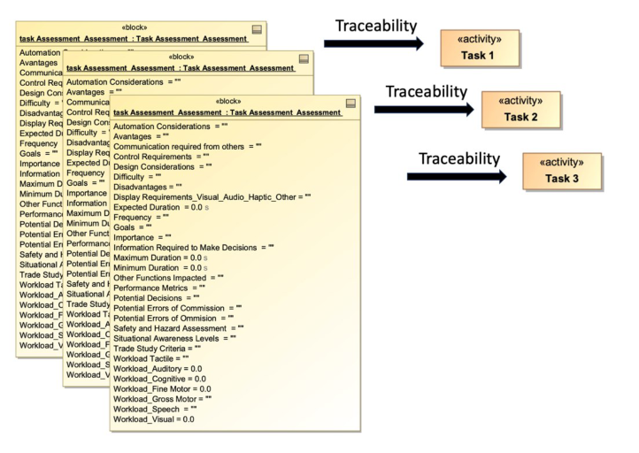
Task Level Analysis Model Completing the task analysis in the model expands on the function level analysis model completed in the previous step. The inputs to the task analysis are all previously discussed documents and the function level analysis, and when possible, identified and tailored task parameters of interest (Table 1). Figure 6 displays a basic model of tasks allocated to the operator and functions allocated to the system. This is a basic version of a function level analysis output model. Now that operator tasks are assigned in the model, the task analysis model will analyze each task. A SysML block is created with value properties representing the selected task parameters of interest from Table 1.
An instance of this block is created and the analysis is executed and task data is entered through the model instance. MBSE tools allow for a tabular view and manipulation of this data through an instance table which can be exported to excel for non-MBSE consumers of the information. This method allows for traceability across all impacted system elements, communication across stakeholders, and provides a single source of truth (Figure 7). The
Task Analysis: A Model Based Human Systems Engineering Approach 17
tabular analysis is augmented by, or augments, additional diagram-based models that support visualizations and modeling of task-related data.
Figure 6: Function level analysis output.Figure 7: Task instance traced to operator task.
Additional research is often required for automation. Behavioral diagrams including the activity diagram, state machine diagram, and sequence diagram can be used to capture how a task could be performed at various levels of automation (Sheridan & Verplank, 1978). These diagrams can convey human-automation interaction variables of interest such as contextual automation reliability, information delivered by automation, automation confidence rating, automation decisions, level of information aggregation,
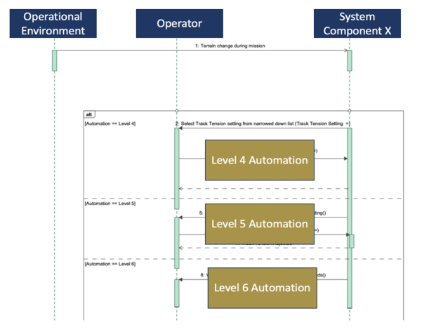
how automation is calculating or making a conclusion, decisions or recommendations, and level of situational awareness. Figure 8 provides A high-level representation of this. The sequence diagram is used to convey task-related exchanges between the different actors in the exchange.
The approach shown in Figure 8 demonstrates an event in the operational environment triggering the system to make a settings adjustment.
Figure 8: Automation analysis sequence diagram.
The diagram shows the system providing the user with three options at different levels of automation to adjust the same setting. At the level 4 option, the system provides the user a list of two choices, the level 5 automation provides the user a single recommendation, and the level 6 automation gives the user 5 seconds to veto before the system makes the recommended setting adjustment. This information could also be represented into three distinct sequence diagrams for clarity. The human system engineer and MBSE team will ultimately decide on the best approach for modeling specific task-related content. SysML has the capability to provide dynamic configurations and automation models interconnected through different state machine, activities, and sequence diagrams.
CONCLUSION
This paper introduced a novel approach to Model-Based Human Systems Engineering (MBHSE), leveraging SysML to conduct and capture Mission Task Analysis (MTA) data. By integrating detailed human-centered information into existing MBSE models, this method addresses critical gaps in traditional systems engineering practices. The approach demonstrates
Task Analysis: A Model Based Human Systems Engineering Approach 19
how a comprehensive MTA can systematically analyze operator-system interactions, informing system design and improving overall performance. This work contributes to the field by structuring how human factors are incorporated into the MBSE process, enhancing traceability, and fostering collaboration among stakeholders. The resulting models enable a more comprehensive understanding of system behavior by accounting for both technical and human elements, ultimately supporting more effective design decisions.
REFERENCES
Aleksandraviˇcien˙e, A., & Morkeviˇcius, A. (2021). MagicGrid® Book of Knowledge: A Practical Guide to Systems Modeling using MagicGrid from Dassault Systèmes (2nd ed.). Kaunas, Lithuania: No Magic, Inc. ISBN: 978-609-454-554-2. Friedenthal, S., Moore, A., & Steiner, R. (2014). A practical guide to SysML: The
systems modeling language (3rd ed.). Morgan Kaufmann. Guyton, Z., Pierson, K., Garay, T., Novitzky, M., McLaughlin, A., Rovira, E.
(2022). The Impact of Role Authority and Communication Initiative on HAT Outcomes. Proceedings of the Human Factors and Ergonomics Society Annual Meeting. Volume 66, Issue 1. International Council on Systems Engineering. (2007). MBSE Initiative. International Council on Systems Engineering. (2023). INCOSE systems engineering handbook: A guide for system life cycle processes and activities (5th ed.). John Wiley & Sons. O’Neill, T. A., McNeese, N. J., Barron, A., & Schelble, B. (2022). Human–autonomy
teaming: A review and analysis of the empirical literature. Human Factors, 64(5), 904–938. Sheridan, T. B., & Verplank, W. L. (1978, June 19–21). Human and computer control of undersea teleoperators [Paper presentation]. 14th Annual Conference on Manual Control, Cambridge, MA, United States.
LISTED IN THE AHFE DIGITAL BOOKSTORE CATALOGUE
Explore the complete digital volume
Creativity, Innovation and Entrepreneurship
Read this individual research paper free through the original publisher, or explore the full digital proceedings book.
ISBN 978-1-964867-42-7
Explore this ISBN in the AHFE Bookstore ↗Listed in the July 2026 bookstore catalogue; search by ISBN to confirm current availability · Digital book purchase optional