Sean Bumgarner, Sarah Rudder (2025). Optimizing Industrial Forklift Human-Machine Interface (HMI) Position. In: Intelligent Human Systems Integration (IHSI 2025): Integrating People and Intelligent Systems. AHFE Open Access, vol. 160, pp. 406–415. https://doi.org/10.54941/ahfe1005845
In a freight system there are many pieces of equipment that compose a system context. The system of interest for our examination is less than truckload (LTL) assets. This paper extends previous research of the tractor fleet to the dock fleet comprised of forklifts and operators. Forklifts are used to transport heavy shipments (i.e., fixed assets) inside a warehouse facility. Electronic documentation of these shipments determines trailer manifests, informs customers on freight location, and observes service constraints in real-time. Placement of incoming freight (i.e., warehouse stock) is communicated to forklift operators via an electronic tablet to enable tasking. The tablet displays workflow and informs the operator where to dock or load freight being processed. Finally, we must understand how the forklift operator interacts with the screen. The luminous intensity, luminous flux, luminance, and illuminance resulting from the tablet placement are used to calculate screen glare and realize necessary adjustments. Methods utilized for this research include analysis of device design alternatives, mounting options, and operator visibility. Interviews were conducted to assess perceived distractedness by the operators. This research concludes with a recommendation for tablet mount location that will maximize forklift operation effectiveness within the LTL system context.
This research examines how the placement of a tablet within the forklift cab affects operator performance and safety. The study investigates design alternatives and evaluates optimal tablet mounting locations to mitigate glare, enhance visibility, and increase readability. This examination highlights and improves the human systems integration (HSI) of a forklift operator. Core systems engineering (SE) processes were conducted to quantify screen brightness. The requirements, structure, and parametrics were built using a reproduceable and generalized model for the driver interface mount location considering human machine interface (HMI) principles.
An operator must execute standard activities for a particular workflow. Instructions for this tasking is received via an HMI. The driver must be able to reach the tablet. Little research has been done on how interface mounting and screen location impacts operator performance and safety.
Optimizing Industrial Forklift Human-Machine Interface (HMI) Position 407
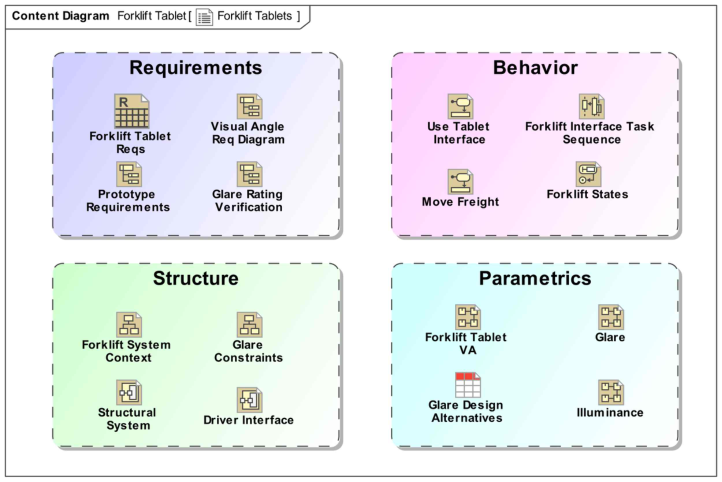
Figure 1: Content diagram for MBSE implementation.
These devices provide business productivity reporting, reweight information for proper pricing and rating, and analyze forklift movement. However, the tablet may decrease operator safety by introducing a visual distraction. Discomfort glare is mainly influenced by the brightness of the light source and angel between the directions of a glare source and with the line of sight of an eye (Bangali, 2018).
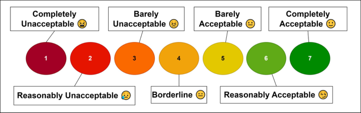
Figure 2 shows assessment ratings for each tablet based on deBoer’s scale (deBoer & van Heemskerck Veeckens, 1955). A rating of five (5) or greater is an acceptable result for the HMI.
Figure 2: Conceptualization of deBoer’s glare rating (adapted fromSte-Croix et al., 2010).
Installation should account for distance from the operator and the screen viewing angle (VA) [i.e., visual angle] to protect employees from discomfort
408 Bumgarner and Rudder
glare. The objective of this study is to mitigate operator tablet interaction risks when completing standard tasks.
The VA of the operator is first evaluated with pixel resolution of liquid crystal display (LCD) screens for several similar design options. LCDs reduce the illumination that meets the eye in comparison to cathode-ray tube (CRT) screens (Anupama et al., 2014). Distance between the operator and HMI is assumed to be 36 inches based on empirical measurements from forklift cabs.
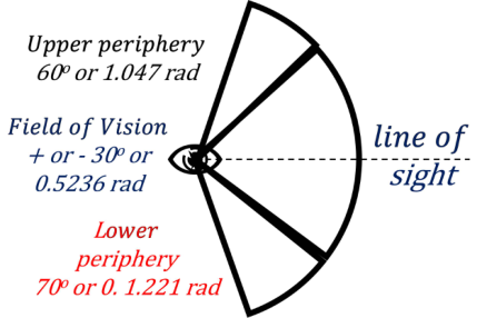
Figure 3 represents recommended angles between operator line of sight and the display location.
Figure 3: Line of sight for forklift operators (adapted from Williams and Boyne, 2010).
RESEARCH APPROACH Requirements are the foundation of system architecture and form the basis of the architecture definition (INCOSE, 2023). They must be linked to the satisfying value properties for verification. Value properties are owned by the system of interest (SoI) and constraints are established. Figure 4 shows the VA requirement.
Figure 4: VA requirement and relationships.
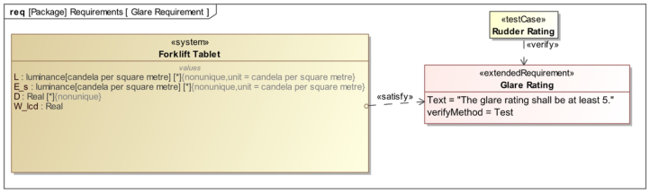
Figure 5 shows the glare requirement. The forklift driver needs a clear line of sight to operate the vehicle (e.g., position, tilt, lower, raise blades). No interaction with the tablet is required during the use of the forklift. A ‘barely acceptable’ rating positions the screen in the driver’s lower peripheral.
Optimizing Industrial Forklift Human-Machine Interface (HMI) Position 409
Figure 5: Glare requirement and relationships.
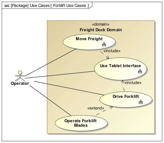
Figure 6 contextualizes the forklift domain and external entities that participate in the use cases. These verb-phrases describe high-level functions of the system that must be invoked for all requirements to be satisfied in design. In this example, the driver performs the Drive Forklift use case and by inclusion, executes the Use Tablet Interface behavior.
Figure 6: Forklift system use cases.
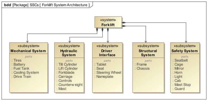
Figure 7 shows the structural architecture of the forklift system, subsystems, and components with HSI aspects. This diagram shows the tablet as a part property of the driver interface and gives the viewer insight into other subsystems that perform safety functions.
410 Bumgarner and Rudder
Figure 7: Forklift system context.
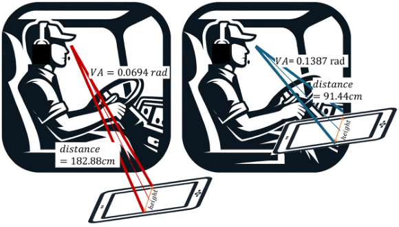
Figure 8 represents an adequate tablet orientation to meet VA requirements at the measured distances. The initial VA calculations and verification are shown in the author’s previous work using Eq. (1) [Bumgarner et al., 2024].
Figure 8: VA for initial (left) and adjusted (right) tablet locations (Bumgarner et al., 2024).Equation reproduced from the original PDF.
screen height 2 · screen distance
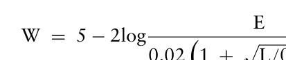
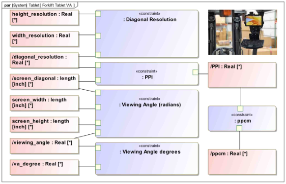
Figure 9 shows the VA calculation in an executable model. Eq. (2) shows deBoer’s glare rating.
Equation reproduced from the original PDF.
θ0.46 (2)
0.02
1 + p
L/0.04
Optimizing Industrial Forklift Human-Machine Interface (HMI) Position 411
Figure 9: Forklift tablet VA calculation.
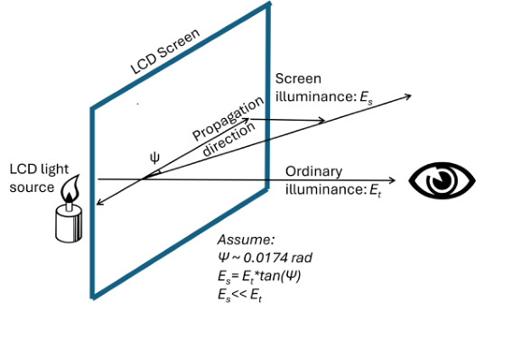
To adapt deBoer’s glare rating for a Liquid Crystal Display (LCD) screen the propagation angle (9) must be understood. The relationship between the illuminance (Es) of the screen and the illuminance of the tablet light source (Et) is described by Eq. (3)
Es = Et · tan (9) (3) LCD screens do not propagate light directly towards the user which baselines the adjustment of deBoer’s rating (den Boer, 2011). The translated rating maintains the light measurement system using LCD screen attributes shown in Figure 10.
Figure 10: A rendering of propagation direction and angle (adapted from deBoer, 2011).
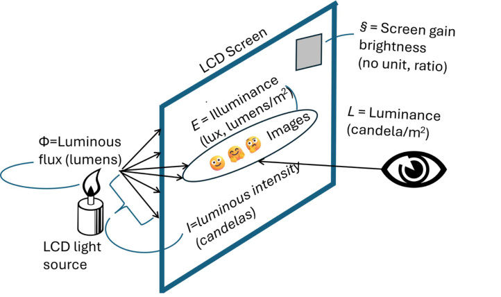
Investigating the effect of the screen flux, luminance, intensity, illuminance, and gain variables enables the Rudder Rating derivation (Bumgarner et al.,
412 Bumgarner and Rudder
2024). Figure 11 provides a visual representation of the glare sustained by the operator.
Figure 11: Light measurements (Bumgarner et al., 2024).
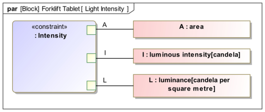
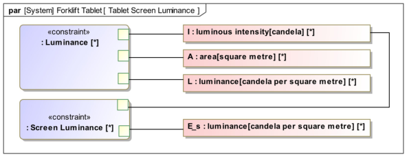
Eq. (4) is used to calculate the LCD screen intensity (I).
I = A · L (4) The input variables for related calculations are captured in the model to resolve parametrics simultaneously for all forklift tablet alternatives. Figure 12 shows the LCD screen intensity calculation in an executable model.
Figure 12: LCD screen intensity calculation.
If the user does not adjust the brightness feature on the tablet, operational gain (§) is assumed to be one (1) and has no impact on the driver’s viewability. Eq. (5) is used to calculate the LCD screen luminance.
Optimizing Industrial Forklift Human-Machine Interface (HMI) Position 413
Equation reproduced from the original PDF.
Figure 13 shows the LCD screen luminance calculation in an executable model.
Figure 13: LCD screen luminance calculation.
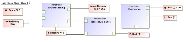
Eq. (6) shows the derived calculation for the LCD screen glare rating (i.e., Rudder Rating).
Equation reproduced from the original PDF.
θ0.46 (6)
0.02
1 + p
L/0.04
Figure 14 shows the Rudder Rating calculation in an executable model with all assumptions and inputs from previous equations.
Figure 14: LCD screen glare rating calculation.
RESEARCH RESULTS Research results are anticipated to determine tablet location within a forklift that optimizes HMI line of sight considerations while meeting viewability and reachability requirements.
Table 1 shows specific tablet types that were considered, the relevant specifications, and the resulting VA. From the verification results, there are two (2) design alternatives that require further investigation for determining the optimal option. The Samsung Exynos and Zebra ET45 tablets satisfy the VA requirement and will be assessed further for adequate glare rating.
414 Bumgarner and Rudder
Table 1. VA results for tablet design alternatives.
Table available in the original PDF paper.
Table 2 shows that the Zebra ET45 tablet satisfies the glare rating requirement of greater than five (5), while the Samsung Exynos fails to meet this acceptable standard.
Table 2. Glare rating results for tablet design alternatives.
Table available in the original PDF paper.
CONCLUSION
The adjusted calculation, the Rudder Rating, based on LCDs aligns with deBoer’s original rating scale for screen glare. From the alternatives originally considered, the Zebra ET45 device is the sole option that satisfies the visual angle, distance, and glare HSI requirements. These parametrics are meant to optimize design for operator safety. A model-based approach to trade study analysis is a viable solution for determining tablet metrics and verifying requirements.
FUTURE RESEARCH Future research will consider the effects of LCD screen brightness for discomfort glare in an otherwise dark operational environment, brightness modes available for electronic devices, and the influence of dark mode screens.
REFERENCES
Anupama, V., Divya, P., Gayathri, A., & Soman K. P. (2014). Automatic anti-glare system for night time driving using liquid crystal screens. International Journal of Research in Engineering and Technology, 03(19), 202–205. https://doi.org/10. 15623/ijret.2014.0319036 Bangali, J. (2018). Discomfort glare prediction by using Unified Glare Rating.
Australian Journal of Electrical and Electronics Engineering, 15(4), 184–191. https://doi.org/10.1080/1448837X.2019.1568670 Bumgarner, S., Rudder, S., Gallegos, E. E., & Daily, J. (2024). Human factors engineering considerations for mounting internal interfaces in heavy vehicles. HFES Conference. Sage Publishing.
Optimizing Industrial Forklift Human-Machine Interface (HMI) Position 415
deBoer, J. B. & van Heemskerck Veeckens, J. F. T. (1955.) Observations on discomfort glare in street lighting. Proceedings of the CIE, Zurich. den Boer, W. (2011). Active Matrix Liquid Crystal Displays: Fundamentals and Applications. Elsevier Science. https://books.google.com/books?id= EdEzJYJFyU0C International Council on Systems Engineering (INCOSE). Systems Engineering
Handbook. (2023). 5th ed. Wiley. Ste-Croix, C., Morton, A., & Angel, H. (2010). Canadian Ranger Rifle: Human factors requirements validation (DRDC Toronto CR 2010-174). Defense Research and Development Canada – Toronto. Williams, K. & Boyne, S. (2010). AMMPHS trial report CFB Valcartier. Human
Systems, Incorporated.
LISTED IN THE AHFE DIGITAL BOOKSTORE CATALOGUE
Explore the complete digital volume
Intelligent Human Systems Integration (IHSI 2025): Integrating People and Intelligent Systems
Read this individual research paper free through the original publisher, or explore the full digital proceedings book.
ISBN 978-1-964867-36-6
Explore this ISBN in the AHFE Bookstore ↗Listed in the July 2026 bookstore catalogue; search by ISBN to confirm current availability · Digital book purchase optional