Andres Vanhooydonck, Jochen Vleugels, Marc Parrilla, Phil Clerx, Regan Watts (2024). Optimizing high accuracy 8K LCD 3D-printed Hollow Microneedles: Methodology and ISO-7864:2016 Guided Evaluation for Enhanced Skin Penetration. In: Health Informatics and Biomedical Engineering Applications. AHFE Open Access, vol. 142, pp. 70–81. https://doi.org/10.54941/ahfe1005072
Microneedle research has surged due to its potential for user-friendly and painless drug delivery. Their ability to pierce the skin and adaptability to skin surfaces underscore their relevance to ergonomic drug delivery systems. Therefore rapid, precise and affordable prototyping is crucial for the advancement of this research field. Among fabrication techniques, 3D printing remains the most agile, particularly with the recent technological progress in high precision 8K LCD printers, providing superior geometric quality. This study focuses on optimizing hollow microneedle designs and conducting ISO 7864:2016 (Sterile hypodermic needles for single-use requirements and test methods)-guided testing to enable objective comparisons among structures. Specifically, relevant features, including hollow needle geometries, tip angles, wall thicknesses and print settings of microneedles, are investigated using a high-resolution liquid crystal display (LCD) printing platform. In the absence of specific ISO standards for transdermal microneedles, this research aims to establish guidelines modelled after ISO-7864:2016 for hypodermic needles. A detailed exploration of a low-cost, accessible test setup design is presented. This contributes to the establishment of benchmarks for microneedle design and evaluation practices through ISO-guided testing methodologies. Beyond scientific contributions, these efforts aim to ensure safer and more effective microneedle applications in healthcare.
Microneedle technology has emerged as a promising avenue in the field of healthcare, offering transformative potential in various applications (e.g. drug delivery and sensing) (Himawan et al., 2023). These micron-sized needles hold immense promise, facilitating less invasive procedures (Friedel et al., 2023), enabling customized medicine delivery (Detamornrat et al.,
Optimizing High Accuracy 8K LCD 3D-Printed Hollow Microneedles 71
2023), reducing patient discomfort (Ebrahiminejad et al., 2022), and enabling real-time monitoring (Parrilla, Detamornrat et al., 2023), among other advantages (Saifullah and Faraji Rad 2023). The amalgamation of agile methodologies and innovative technologies, particularly 3D printing, has bolstered this field, paving the way for enhanced precision and efficiency in medical interventions (Parrilla, Vanhooydonck et al., 2023).
In the absence of standardized testing protocols for microneedles (MNs) and transdermal devices, the significance of ISO (International Organiza- tion for Standardization) compliance becomes evident. Notably, while there exists a standardized evaluation framework for hypodermic needles (ISO 7864:2016, Sterile hypodermic needles for single-use requirements and test methods), the absence of a specific standard for MNs underscores the impor- tance of benchmarking against established technical standards to assess their performance accurately.
Traditionally, MNs have been manufactured using various techniques such as lithography, micro-molding, injection molding and laser ablation (Aldawood, Andar, and Desai 2021), each method with its limitations and advantages. However, the advent of 3D printing has revolutionized this landscape, offering unparalleled agility and high accuracy (Mathew et al., 2021; Rajesh et al., 2022) especially when dealing with hollow MNs that are notoriously hard to manufacture. The emergence of 8K printing technology, boasting accuracy levels down to 22µm, with its increasingly dense pixel res- olution and the potential for even higher resolutions like 12K and 14K, has ushered in a new era of extreme precision.
In this paper, we delve into the methodologies employed for optimizing the design of hollow MNs to minimize needle penetration force when fabricated using a high-precision 8K LCD 3D-printing platform, aligning our evalu- ation with the ISO 7864:2016 standard. This research specifically targets standalone needles, a deliberate choice aimed at facilitating comprehensive and detailed testing methodologies. The insights derived from this focused study can later be extrapolated to advance the development of patch-based MN systems for future medical applications.
METHODS
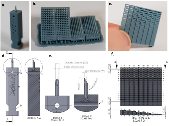
Microneedle Design and Configurations Geometry: MNs typically find use in patch configurations (Makvandi et al., 2021), but this research focuses solely on testing individual needles (Fig. 1a). While various hollow MN shapes like conical, pyramidal, and bullet-shaped have been explored (Makvandi et al., 2021), the more traditional hypoder- mal needle shape—a hollow cylinder with a slanted top surface for skin penetration—has often been overlooked. These needles, with their efficient geometry, can be small yet effective. The needle’s geometry comprises an internal hole combined with the selected wall thickness, determining its man- ufacturability, Table 1 illustrates the critical geometric considerations that were included in the design of these MNs. These criticalities are described below. The design of the MNs is shown in Fig. 1. a, d, e and the design files can be downloaded in the online repository.
Height: The ideal MN length for transdermal drug delivery is 1mm, as it effectively penetrates the stratum corneum while avoiding nerve endings and blood vessels (Aich, Singh, and Dang 2022; Ganeson et al., 2023; Jung and Jin 2021). This length is particularly suitable for hollow MNs, which have been shown to improve drug delivery by penetrating past the stratum corneum (Sivamani et al., 2009). MNs, including hollow ones, have been pro- posed as a strategy to breach the stratum corneum barrier and enhance skin permeability for various therapeutic molecules (Tuan-Mahmood et al., 2013). The use of MNs for transdermal drug delivery, including their types, fabrica- tion techniques, and safety aspects, has been extensively reviewed (Dharadhar et al., 2018).
Inside diameter of needle (ID): The MN’s internal cavity can serve a multi- tude of purposes, for example allowing for the delivery of liquids or reagents, or extraction of bodily fluids. To gauge the manufacturable limits of the inter- nal hole diameter using the Phrozen Sonic Mini 8K (Phrozen Technology Co., Ltd, Taiwan) and 8K grey resin, a range of hole diameters (0.05 mm – 0.90 mm) and hole depths (0.50 mm – 4.00 mm) were established on a benchmark by triplicates, printed at a 45
angle to the build plate, the most suitable print orientation for this specific geometry (Fig. 1.c,f). Since the geometry of the microneedle is dissimilar, a different print orientation might be more suitable, the effect of this will later be explored. It should be noted that the most significant factors for this test are the selected resin and the cleaning procedure.
Figure 1: (a) 3D-printed microneedle design used for testing. With configuration mark- ing (a) and a notch for mounting in the test setup. (b) Wall thickness benchmark printed in double at a 45◦angle and parallel to the 3D-printers build plate. (c) Internal diameter benchmark shown in hand for scale. (d) Technical drawing of MN design. (e) A section view (AA) is displayed to show internal channelling for resin extraction during wash- ing, also displayed in det. (f) Technical drawing of internal diameter benchmark with cross section.
Optimizing High Accuracy 8K LCD 3D-Printed Hollow Microneedles 73
The Benchmark shows the possibility of reliably producing holes down to 0.50 mm diameter, considering a hypothetical MN height of 1.00 mm, accompanied by a 1 mm patch substrate base resulting in a 2.00 mm hole length.
Henceforth, a minimum diameter of 0.50 mm will guide subsequent designs. For other hole lengths, the online repository offers reference points, indicating a minimum inside diameter of up to 0.35 mm for the smaller hole length.
Wall thickness (WT): To achieve the smallest needle diameter, a printed benchmark test was devised (fig. 1.b.), varying wall thickness (WT) from 50 µm to 500 µm in 50 µm increments. This benchmark was printed both parallel to the 3D printer’s build plate and at a 45
angle. While all con- figurations were successfully printed, it is noteworthy that the 50 µm wall thickness was deformed and remarkably fragile. Hence, the minimum viable wall thickness for the hollow MN was established at 100 µm, a value adopted for subsequent tests.
Outside diameter (OD): Determining the minimum outside diameter (OD) involved calculating OD = ID + 2 × WT using the benchmark. For our selected geometry, the minimum OD derived from this formula stood at 700 µm. The impact of wall thickness is within the range of 50 µm to 250 µm. (Fig. 1.e.)
Angle (AN): The angle of the needle tip plays a pivotal role in sharpness. While sharper angles facilitate easier penetration, they render the 3D-printed MN more brittle. Therefore, sharpness becomes a balancing act between pen- etration force and needle strength. Our tests will span angles from a 90
blunt tip to a 15
angle (as detailed in Table 1). It is important to note that the angle is constrained by the ratio between the diameter and the height of the needle. For instance, with a 1:1 ratio, the maximum tip angle can only reach 45
. (Fig. 1.e) 3D print variables: Optimal sharpness in 3D-printed MNs requires meticu- lous selection of 3D printer settings. Utilizing a Phrozen Sonic Mini 8K printer and Chitubox slicer (Chitubox, Shenzhen, China), various layer heights (LH), print orientations (PO), and the impact of anti-aliasing (AA) were investi- gated. One needle was printed with an orientation perpendicular to the build plate (PO3). The other two were printed at 45
and −45
angle to the build plate leading to the corresponding 45
needle bevel being vertical (PO1) and horizontal (PO2) to the build plate. Anti-aliasing helps in smoothing out print imperfections by reducing pixel-based artifacts. The choice of Phrozen Aqua 8K 3D Printing Resin was made for its precise reproduction capabilities and ability to produce small internal holes. Selected variables can be found in Table 1.
Default dimensions: In this study, a standard needle was fabricated to serve as a baseline for comparing other microneedle configurations. This nee- dle has the following configuration; a height of 3.5 mm, a wall thickness (WT) of 0.1 mm, an outside diameter (OD) of 0.7 mm, and an angle (AN) of 45
.
Table 1. Overview of the variables selected for testing.
) Layer Height (mm) Anti Aliasing Print Orientation (
) AN2 AN3 AN4 AN5 LH1 LH2 LH3 AA1 AA2 PO1 PO2 PO3
20.0 15.0 10.0 0.01 0.02 0.05 No Yes 45
-45
90
The fabrication adhered to standard print settings, including a layer height (LH) of 0.02 mm, a print orientation (PO) of 90
relative to the build plate, and the absence of Anti-aliasing (AA) techniques. Several configurations will be tested while these variables remain constant except for the one variable that is being tested in the specified configuration (Table 1).
Post-Printing Protocol After the printing phase, a detailed cleaning and curing protocol followed. This involved specific steps: (1) Allowing uncured resin to drip off by mount- ing the build plate at an angle for 5 minutes. (2) Utilizing an isopropyl-alcohol (IPA) spray to eliminate trapped or excess resin. (3) Submerging the needles in an IPA bath for 5 minutes. (4) Placing the prints in a Form Wash (Formlabs, Massachusetts, USA) filled with IPA for 10 minutes, followed by another 20 minutes in a second Form Wash. (6) Rinsing the prints with deionized water and finally (7) curing them in a Form Cure (Formlabs, Massachusetts, USA) at 40
C for 30 minutes. Throughout these stages, meticulous care was exercised to prevent the fragile MNs from blunting.
Additionally, for effective cleaning after printing, the MNs are hollowed within the main body of the fixture. This design integrates a horizontal open shaft, allowing unobstructed access to the internal opening of the needle on both ends (Fig. 1e). This facilitates efficient resin drainage and enables iso- propyl alcohol (IPA) to access the hollow space, ensuring thorough cleaning processes.
Experimental Setup for ISO Penetration Force Testing of Microneedles The conventional assessment of MNs traditionally relied on porcine skin (Ranamukhaarachchi et al., 2016) or parafilm tests (Larrañeta et al., 2014), validating mainly the needle’s ability to pierce and its penetration depth. However, this method lacks the capacity to yield objectively comparable results for benchmarking against standard hypodermic needles. To bridge this gap, our research aims to establish a standardized test setup following ISO 7864:2016. Notably, while ISO standards exist for hypodermic needles, none specifically address the necessary testing methods for validating MN or transdermal needle sharpness. Consequently, our devised test setup draws inspiration from available ISO standards to address this critical methodolog- ical void. Aligned with ISO 7864:2016 guidelines, an intricately engineered testing apparatus was designed to objectively assess the sharpness of diverse
Optimizing High Accuracy 8K LCD 3D-Printed Hollow Microneedles 75
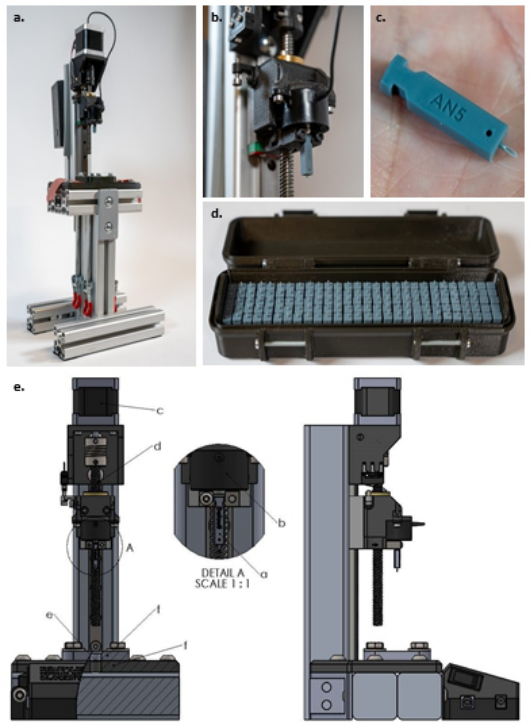
MN configurations presented in Table 1. This apparatus ensures compliance with established standards by rigorously evaluating MN samples’ piercing capabilities through a silicone membrane clamped between two plates while measuring the required force (Fig. 2.e.f.).
Figure 2: (a) This image showcases the test apparatus developed for evaluating the sharpness of various microneedle configurations. (b) It features a close-up view of the microneedle, positioned just beneath the load cell’s measurement point. The load cell is integrated into a linear movement mechanism, located directly under the end stop switch, ensuring precise measurements. (c) The image also shows the AN5 micronee- dle configuration, mounted on the fixture body and displayed in the palm of a hand for scale reference. (d) Finally, the photograph presents a comprehensive display of all the microneedle configurations tested in this study, organized into sets of five for easy comparison and analysis. (e) Comprehensive Technical Diagram of a Microneedle Sharpness Testing Setup: This detailed image showcases a front view (bottom left) and a side view (bottom right) of a custom-designed apparatus for evaluating microneedle sharpness, aligned with ISO 7864:2016 standards. Key features include a magnified view of the microneedle holder jig (Detail A), and labeled parts: the microneedle (a), loadcell (b), motor (c), linear movement mechanism (d), silicone membrane (e), and the two fixture plates (f) securely clamping the membrane.
We deliberately opted for the 0.5 ± 0.05 mm silicone membrane with a hardness of 50 ± 5 Shore A due to its thinness within the substrate options outlined in ISO 7864:2016 D2.2. The piercing process strictly adheres to the recommendations in ISO 7864:2016 D2.1, employing a gradual needle descent at a velocity of 100 mm/min.
Constructing this specialized testing apparatus shown in Fig. 2.a. involved integrating aluminium extrusion profiles and 3D-printed components. The silicone substrate fixation was regulated using toggle clamps, ensuring con- sistent force application throughout testing. Precise linear movement control at a predetermined constant rate was achieved through an Arduino UNO interfaced with a DRV8825 motor driver, governing a NEMA 17 Stepper motor (Fig. 2.e.c.). Incorporating an FC2231 Loadcell (Fig. 2.e.b.) with a 50N range and a high-resolution 16-bit ADS1115 Analog-to-Digital Con- verter (ADC) significantly enhanced measurement accuracy. Remarkably, the total fabrication cost of this comprehensive setup remained under €300, and detailed design files are available in the online repository for reference and replication.
For simplified handling and testing, the needle is 3D-printed atop a fix- ture body (Fig. 1) This body serves two purposes: (i) configuration distinct text markings for identification and (ii) featuring two grooves to secure the MN firmly within the test setup. Focusing solely on assessing tip sharp- ness, the length of the needle is extended to a height 3.5 mm to ensure optimal penetration into the flexible 0.5 mm silicone substrate, preventing substrate flex and ensuring precise and complete penetration through the substrate.
During insertion into the test setup, the needle loosely positions itself beneath the load cell. As the load cell starts descending, any contact with the substrate prompts the needle to rise, initiating measurements and driving through a 2mm penetration depth to ensure complete tip penetration.
Each configuration is printed in 5-fold, and each print is tested 5 times. This results in 25 measurements per configuration as well as data reveal- ing potential blunting of the tip and differences between configurations and separate 3D-prints.
RESULTS AND DISCUSSION
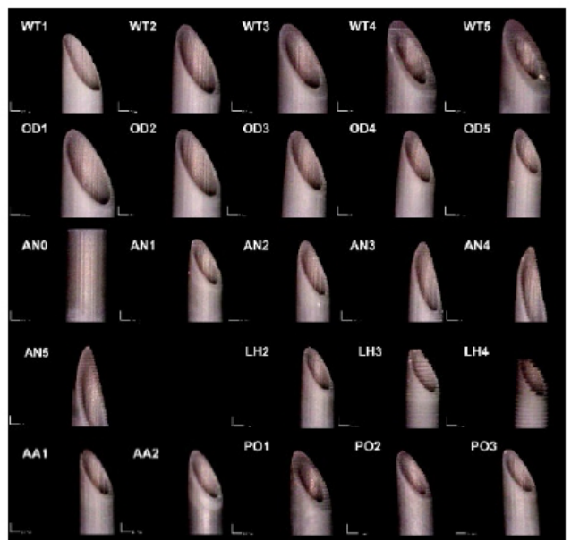
Microneedle Close-Up Images The MNs were imaged using a DinoLite AM73915MZTL microscope, while a 3D-printed fixture ensured consistent positioning for imaging accuracy. In Fig. 3, a close-up illustrates the needle tips of each configuration before test- ing. Any visible defects observed are attributed to the printing parameters or settings, or they may have occurred during the washing and curing phases of the print process.
Optimizing High Accuracy 8K LCD 3D-Printed Hollow Microneedles 77
Figure 3: Microscope images of all tested MN configurations, pictures taken horizon- tally at a 45◦angle with frontal lighting. From top to bottom wall thickness (WT), outside diameter (OD), angle (AN), layer height (LH), anti-aliasing (AA) and print orientation (PO). More, full resolution, images can be found in the online repository.
Penetration Force Testing Results Hypodermal Needles: By way of Comparison, 16G, 18G, and 21G hypo- dermal needles were tested in the setup, yielding forces of 0.34 ± 0.01 N, 0.25 ± 0.02 N, and 0.19 ± 0.03 N, respectively, where these values repre- sent the mean force and standard deviation. Each needle was tested 5 times. These exceptionally low standard deviations signify the setup’s remarkable repeatability and consistency, providing an objective basis for comparison (Table 2).
Wall Thickness (WT): When employing a minimum wall thickness of 50µm, it yielded the lowest average peak penetration force of 1.10 N. How- ever, it led to frequent breakage of the needle tip after one or two uses. Other wall thicknesses, ranging from 2.11 ± 0.25 N to 2.32 ± 0.26 N, exhibited closely clustered values, indicating negligible impact on the needle’s penetration behavior (Table 2).
Outside Diameter (OD): A clear correlation emerged between the mea- sured penetration forces and the range of outside diameters tested. The smallest outside diameter of 700µm resulted in the lowest average peak
force of 1.44 ± 0.23 N, while the largest diameter of 1100µm increased to 1.93 ± 0.30 N (Table 2). Angle (AN): Initial testing with a blunt angle of 90
rendered the nee- dle incapable of membrane penetration, registering an average peak force of 11.75 ± 0.31 N. In contrast, AN3 (25
) and AN4 (20
) recorded the lowest forces of 0.76 ± 0.14 N and 0.76 ± 0.23 N during the first penetra- tion. Less acute angles exhibited higher force measurements, showcasing that sharper angles significantly enhance penetration. However, sharper needles demonstrated a substantial increase in standard deviation, indicating unre- liable results. In Fig. 3, it is shown that these sharper needles exhibit slight curvature due to their delicate nature and more frequent tip breakage, con- sequently compromising subsequent measurements. Consequently, the 25
angle proved to offer the best penetration with the most consistent outcomes (Table 2).
Layer Height (LH): Testing encompassed various layer heights from 10 µm to 100 µm. The standard print setting rested at 20 µm due to the 8K resolution of the exposure screen, ensuring a 22 µm pixel accuracy in the x and y direc- tions. This resolution deems 20 µm in the z direction optimal for maintaining consistent print dimensions. LH2 (20 µm) showcased superior outcomes, indicating that lower layer heights result in better print reproduction, enhanc- ing penetration with an average peak force of 1.47 ± 0.14 N during the initial penetration. In Fig. 3, discernible differences in layer height are evident, par- ticularly with 50 µm and 100 µm, displaying signs of inadequate exposure leading to serrated edges (Table 2).
Anti-Aliasing (AA): A comparison between no anti-aliasing (AA1) and anti-aliasing (AA2) revealed that the absence of anti-aliasing yielded better results, with an average force of 1.31 ± 0.39 N compared to 1.49 ± 0.14 N. Notably, AA1 exhibited a high standard deviation of 0.39 N, significantly higher than the 0.09 N for AA2. These findings suggest that anti-aliasing does not significantly influence MN behavior (Table 2).
Print Orientation (PO): PO1, printed with layer lines perpendicular to the needle’s angled surface, resulted in the highest force of 1.74 ± 0.15 N. Conversely, PO2 (layer lines parallel to the needle angle’s surface) and PO3 displayed similar forces of 1.40 ± 0.16 N and 1.45 ± 0.12 N, respectively. This implies that orienting the needle with the bevel perpendicular to the build plate diminishes penetration capabilities (Table 2).
Blunting Each needle underwent five consecutive tests to assess blunting effects over multiple uses. The average force of the fifth penetration was subtracted from the average force of the initial penetration, indicating the average blunting displayed in Table 2. On average, the needles exhibited an 8 ± 13% blunting effect by its fifth consecutive use.
Optimizing High Accuracy 8K LCD 3D-Printed Hollow Microneedles 79
Table 2. Comprehensive analysis of microneedle penetration forces: this table presents detailed data on penetration forces for various microneedle configu- rations, based on extensive testing. Each configuration’s average penetration force is calculated from 25 individual measurements, encompassing 5 tests on each of 5 MN’s. The table includes average penetration force, average and standard deviation of the first penetration force, and the change in force from the 1st to the 5th penetration (degradation). The variables tested include wall thickness (WT), outer diameter (OD), angle (AN), layer height (LH), anti- adhesive application (AA), and print orientation (PO).a Raw data and more graphs can be found in the online repository.
Table available in the original PDF paper.
Average 1st
Configuration Name
Value of Variable
Standard Deviation 1st
Degradation Average 5th
Average Penetration Force (N)
Penetration Force (N) Penetration (N)
Penetration – Average 1st (N) WT1 0.05 mm 1.059 1.1 0.28 0.00c WT2 0.1 mm 2.184 2.18 0.43 0.13 WT3 0.15 mm 2.038 2.13 0.22 −0.11 WT4 0.2 mm 1.931 2.11 0.25 −0.26 WT5 0.25 mm 2.131 2.32 0.26 −0.34 OD1 1.1 mm 1.792 1.93 0.30 −0.24 OD2 1 mm 1.754 1.84 0.09 −0.17 OD3 0.9 mm 1.637 1.74 0.16 −0.13 OD4 0.8 mm 1.525 1.65 0.16 −0.15 OD5 0.7 mm 1.268 1.44 0.23 −0.21 AN0 90
10.78 11.6b 0.31 −1.83 AN1 30
0.92 0.99 0.30 −0.05 AN2 25
1.169 1.35 0.22 −0.28 AN3 20
0.749 0.76 0.14 −0.04 AN4 15
0.763 0.76 0.23 0.04 AN5 10
1.000 1.03 0.27 −0.04 LH1 0.01 mm 1.687 1.8 0.10 −0.15 LH2 0.02 mm 1.298 1.47 0.14 −0.26 LH3 0.05 mm 2.355 2.2 0.22 0.24 AA1 No 1.183 1.31 0.39 −0.01 AA2 Yes 1.394 1.49 0.09 −0.15 PO1 45
vert. 1.625 1.74 0.15 −0.17 PO2 -45
hor. 1.342 1.4 0.16 −0.10 PO3 90
1.379 1.45 0.12 −0.10
aThe dimensions for the needles except for the configuration value are a height of 3.5 mm, a wall thickness (WT) of 0.1 mm, an outside diameter (OD) of 0.7 mm, and an angle (AN) of 45
. The fabrication adhered to standard print settings, including a layer height (LH) of 0.02 mm, a print orientation (PO) of 90
relative to the build plate, and Anti-aliasing (AA) not applied. bNeedle did not penetrate but only stretched membrane. cNone of the 5 tested needle configurations were durable enough to withstand 5 tests.
CONCLUSION
This in-depth study meticulously optimized high-precision 8K LCD 3D- printed hollow microneedles and provided a testing methodology according to ISO 7864:2016 standards to properly evaluate skin penetration capabil- ities. Our study rigorously investigated key MN features using the Phrozen Sonic Mini 8K, ranging from hollow needle geometries, tip angles, wall thick- nesses, to print settings, vital for capillary action in fluid extraction and drug delivery. In the absence of specific ISO standards for MNs, our devised
guidelines derived from ISO 7864:2016 offer a comprehensive framework for testing. This approach includes an accessible, cost-effective test setup, introducing consistency across MN evaluations. Our experimental findings yield invaluable insights into MN performance across distinct parameters: (i) a minimum viable WT of 100 µm ensures both successful printing and durability; (ii) low penetration forces correlate with smaller OD; (iii) optimal consistency is achieved at a 25
AN; (iv) enhanced print quality is achieved at 20 µm LH; (v) AA suggested negligible impact on penetration force; and (vi) the use of the PO with layer lines parallel to the needle angle’s surface enhances penetration.
The devised testing apparatus, integrating precision engineering and cost- effective materials, facilitated comprehensive assessments, ensuring reliable comparisons akin to that of established hypodermic needle evaluations. In addition to this, the CAD models of the microneedle designs and the Bill of Materials and CAD files for the testing apparatus have been open-sourced with the community to facilitate future development. Furthermore, recent advancements in printing technology of 12K and 14K printing (Anycubic Photon Mono M5s and M5s Pro, Anycubic, Shenzhen, China), offer even higher resolutions, promising superior accuracy down to the micrometer level, potentially enhancing MN design and functionality.
Overall, the utilization of 3D printing’s agility and accuracy was pivotal, focusing on refining hollow MN designs while conducting ISO-guided testing to objectively benchmark against established standards.
ACKNOWLEDGMENT
The authors would like to acknowledge financial support from the Univer- sity of Antwerp, Bijzonder Onderzoeksfonds (41500). M.P. acknowledges financial support from the Fund for Scientific Research (FWO) Flanders grant 1265223N.
REFERENCES
Aich, Krishanu, Tanya Singh, and Shweta Dang. 2022. “Advances in Microneedle- Based Transdermal Delivery for Drugs and Peptides.” Drug Delivery and Translational Research 12(7): 1556–68. https://link.springer.com/article/10.1007/ s13346-021-01056-8 (January 5, 2024) Aldawood, Faisal Khaled, Abhay Andar, and Salil Desai. 2021. “A Comprehen-
sive Review of Microneedles: Types, Materials, Processes, Characterizations and Applications.” Polymers 13(16): 2815. Detamornrat, Usanee et al., 2023. “Transdermal On-Demand Drug Delivery Based on an Iontophoretic Hollow Microneedle Array System.” Lab on a Chip 23: 2304–2315. Dharadhar, Saili, Anuradha Majumdar, Sagar Dhoble, and Vandana Patravale.
2018. “Microneedles for Transdermal Drug Delivery: A Systematic Review.” Drug Development and Industrial Pharmacy 45(2): 188–201. Ebrahiminejad, Vahid, Philip D. Prewett, Graham J. Davies, and Zahra Faraji Rad.
2022. “Microneedle Arrays for Drug Delivery and Diagnostics: Toward an Opti- mized Design, Reliable Insertion, and Penetration.” Advanced Materials Interfaces 9(6): 2101856.
Optimizing High Accuracy 8K LCD 3D-Printed Hollow Microneedles 81
Friedel, Mark et al., 2023. “Opportunities and Challenges in the Diagnostic Utility of Dermal Interstitial Fluid.” Nature Biomedical Engineering. Ganeson, Keisheni et al., 2023. “Microneedles for Efficient and Precise Drug Delivery
in Cancer Therapy.” Pharmaceutics 2023, Vol. 15, Page 744 15(3): 744. https: //www.mdpi.com/1999-4923/15/3/744/htm (January 5, 2024) Himawan, Achmad et al., 2023. “Where Microneedle Meets Biomarkers: Futuristic Application for Diagnosing and Monitoring Localized External Organ Diseases.” Advanced Healthcare Materials 12(5): 2202066. Jung, Jae Hwan, and Sung Giu Jin. 2021. “Microneedle for Transdermal Drug Deliv-
ery: Current Trends and Fabrication.” Journal of Pharmaceutical Investigation 2021 51:5 51(5): 503–17. https://link.springer.com/article/10.1007/s40005-021- 00512-4 (January 5, 2024) Larrañeta, Eneko et al., 2014. “A Proposed Model Membrane and Test Method for Microneedle Insertion Studies.” International Journal of Pharmaceutics 472(1–2): 65–73. Makvandi, Pooyan et al., 2021. 13 Nano-Micro Letters Engineering Microneedle
Patches for Improved Penetration: Analysis, Skin Models and Factors Affecting Needle Insertion. Springer Singapore. Mathew Essyrose, Giulia Pitzanti, Ana L. Gomes Dos Santos, and Dimitrios A. Lamprou. 2021. “Optimization of Printing Parameters for Digital Light Processing 3D Printing of Hollow Microneedle Arrays.” Pharmaceutics 13(11). Parrilla, Marc, Andres Vanhooydonck, et al., 2023. “3D-Printed Microneedle-Based
Potentiometric Sensor for PH Monitoring in Skin Interstitial Fluid.” Sensors and Actuators: B. Chemical 378: 133159. Parrilla, Marc, Usanee Detamornrat, et al., 2023. “Wearable Microneedle-Based Array Patches for Continuous Electrochemical Monitoring and Drug Delivery: Toward a Closed-Loop System for Methotrexate Treatment.” ACS Sensors 8(11): 4161–70. Rajesh, Netra U. et al., 2022. “3D-Printed Microarray Patches for Transdermal
Applications.” JACS Au 2(11): 2426–45. Ranamukhaarachchi, S. A. et al., 2016. “A Micromechanical Comparison of Human and Porcine Skin before and after Preservation by Freezing for Medical Device Development.” Scientific Reports 6(August): 1–9. Saifullah, Khaled Mohammed, and Zahra Faraji Rad. 2023. “Sampling Dermal Inter-
stitial Fluid Using Microneedles: A Review of Recent Developments in Sampling Methods and Microneedle-Based Biosensors.” Advanced Materials Interfaces 10(10): 2201763. Sivamani, Raja K., Boris Stoeber, Dorian Liepmann, and Howard I. Maibach. 2009.
“Microneedle Penetration and Injection Past the Stratum Corneum in Humans.” Journal of Dermatological Treatment 20(3): 156–59. Tuan-Mahmood, Tuan Mazlelaa et al., 2013. “Microneedles for Intradermal and Transdermal Drug Delivery.” European Journal of Pharmaceutical Sciences 50(5): 623–37.
LISTED IN THE AHFE DIGITAL BOOKSTORE CATALOGUE
Explore the complete digital volume
Health Informatics and Biomedical Engineering Applications
Read this individual research paper free through the original publisher, or explore the full digital proceedings book.
ISBN 978-1-964867-18-2
Explore this ISBN in the AHFE Bookstore ↗Listed in the July 2026 bookstore catalogue; search by ISBN to confirm current availability · Digital book purchase optional