André Kaiser, Norman Hofmann, Heike Hermsdorf (2022). Precision of Marker-Based Finger Tracking for Broad Biomechanical Studies Using 6DOF Targets. In: Digital Human Modeling and Applied Optimization. AHFE Open Access, vol. 46, pp. 79–87. https://doi.org/10.54941/ahfe1001902
In the production the hand is subjected to high loads, because connections between two parts are often done using fasteners. Biomechanical hand models can be found in literature, where systems using single marker tracking showed the highest accuracy. Our system is focused on target tracking, which means tracking of a rigid body with at least 4 markers. The paper therefore describes a 6DOF target tracking procedure and compares the results to a commercial available system within two studies. The first study (n=5) deals with calibrations that are captured for computational determination of anthropometric data. The results show, that the anthropometry is calculated accurate, with e.g. 1.28 mm difference in thickness compared to an anthropometer. The measurement seems reliable with a test-retest variability of less than 10%. The second study (n=5) estimate the accuracy and precision of the fingertips using a design to grasp cylinders. The fingertips penetrate the cylinder 0.8 mm with a RMSE of 2.59 mm. Thus it is possible to measure difference between a gentle and a strong touch.
The hand is a complex system which allows humans to mechanically inte- ract with their surroundings. Especially in production environment the hand and forearm system is subjected to high loads, because connections between two parts are often done using fasteners like clips or plugs. Biomechanical analysis of specific workplaces may provide information to optimize their ergonomic design, but the modelling and capturing of these situations are complicated and time consuming. Biomechanical hand models can be found in broad literature, where specific aspects are described in detail (Houston et al., 2021; Sancho-Bruh, 2011; Cerveri et al., 2007; 2005) from the captu- ring using different technologies, to the definition of model parameters and the motion reconstruction. Mostly there is a trade-off between fast to use and high accuracy. The Dynamicus human model tries to combine a pre- cise and high automated capturing with a precise motion reconstruction. We use an ART DTRACK system which allows automated 6-Dregree of Free- dom (6DOF) target tracking, which means tracking a rigid body with at least 4 markers. Single marker tracking is also possible, but in case of loose the field
of view due to coverings or reflections, the identification of specific markers is problematic, especially in field environments. Consequently models based on single marker tracking, like described in Cerveri et al. (2005), cannot be used. The paper will therefore describe a 6DOF target finger tracking proce- dure, including the designed 6DOF targets and the calibration strategy. The developed method will be compared to ART’s Fingertracking (ART-FTM), including a specific device and software routines (www.ar-tracking.com).
TECHNOLOGY To capture the finger movements, a lot of different technologies are availa- ble. General speaking, optical systems provide greater precisions and no drift regarding position and orientation data, but are prone to occlusion. Because biomechanical studies (especially measuring forces and torques) require high precision and accuracy, we stick with optical systems. Markerless optical systems are less precise compared to marker-based tracking, because the detection is more challenging. Results for Leap-Motion controller and the fingertips are given by Valentini and Pezzuti (2017). They show a mean accuracy of 4-5 mm (which includes the human movement accuracy [Kaiser, 2020; Rüffert, 2017]) and a precision given in 4-5 mm standard deviation. Single marker based systems show higher precision, like shown in Cerveri et al. (2007). This study shows the distance between marker predicted by the model and the one measured by the capture system as Root Mean Square Error (RMSE) and gives a precision of 1.5-2 mm for the index finger and 1.5-3.25 mm for the Thumb. Unfortunately single marker tracking using the A.R.T System is not a useful option, as described earlier. But the ART system provides the ART-FTM (Hillebrandt et al., 2006) based on active Markers, as well as 6DOF target tracking. We will develop our own finger tracking using 6DOF targets and compare it to the ART-FTM.
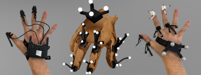
6DOF targets consisting of 4 markers are not available for the fingers. So we designed our own targets with passive markers (diameter 6 mm) and a minimal marker distance of 20 mm, weighting 2 g in total. The 6DOF targets are designed for the right hand, with targets for the palm, the proximal and distal phalanges of three fingers. They stick to the nails using tape and to the proximal phalanges using rubber band. In comparison the ART-FTM is built of two active markers on top of each finger, which are clipped on the distal phalanges. They light up at different times, to allow the system to differentiate between the fingers. Four active markers and the power supply are on top of the palm. This allows tracking of the position and orientation of the palm. Figure 1 shows the ART-FTM as well as our designed 6DOF targets.
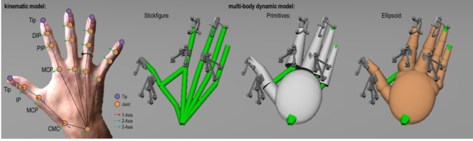
Our kinematic model contains a palm and three phalanges for each finger, all connected by joints. Under the influence of external forces, finger joints move slightly outside the actively controllable degrees of freedom. Thus we use ball joints, to be able to simulate this deformation. Nevertheless, in our motion reconstruction we can reduce the degree of freedom within the joint chain of each finger. So it is possible to use 4 DOF for each finger like descri- bed in the literature, given 2 DOF to each MCP and 1 DOF to each PIP and DIP joint (Sancho-Bru et al., 2011). But it is also possible to use up to 9 DOF
Precision of Marker-Based Finger Tracking for Broad Biomechanical Studies 81
Figure 1: ART-FTM (left) and designed 6DOF targets (middle and right).
for each joint chain. We choose an 8 DOF joint chain with a 2 DOF DIP joint, excluding a rotation along the longitudinal axis, because our marker setup contains two 6DOF targets on each finger. This leads to higher accu- racy for the fingertips and reduces effects of wrong calibrated rotation axes. This approach follows the idea of trusting in sensor data. In comparison the ART-FTM uses a 4 DOF chain for each finger. They calculate the joint angles with their own inverse kinematics. In addition, the phalange length changes during one measurement.
Our multi-body dynamic model includes elliptical truncated cones as geo- metric primitives for each phalange and an ellipsoid as primitive for the palm. Using the hand mass of the Dynamicus and the assumption of a constant den- sity, these primitives allow the calculation of the volume, the center of mass and the moments of inertia. Additional we model the fingertips as ellipsoids, to calculate the distance towards other objects. Figure 2 shows our kinematic and multi-body dynamic model.
Figure 2: kinematic and dynamic model.
To calculate our kinematic and dynamic model we need the following anthropometric data: position of the joints (Wrist, MCP and CMC) within the palm, length of the phalanges and the palm, as well as the thickness and the width of the palm, all joints and the fingertips. In comparison the ART- FTM uses the position of the joints (MCP and CMC) within the palm, the length of each phalange and a radius of each fingertip. This means the fin- gertips are modelled as spheres. A calibration routine is needed to obtain this information (Figure 3).
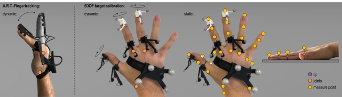
Figure 3: calibration routines for the ART-FTM and our 6DOF target calibration.
The ART-FTM calibration uses a dynamic routine with some assumpti- ons. The distance between the index finger and middle finger influences the radius of the fingertips of all fingers. Movements of the index and middle fin- ger define the MCP joints of both fingers as well as the position of the CMC joint. The length of the fingers defines the length of the phalanges using Lit- tlers (1973) assumption of the Fibonacci ratio. In comparison we try two variations: a dynamic calibration (according to Ehrig et al., 2006) to calcu- late the position of the MCP and CMC joints as the Centre of Rotation (CoR) and a static calibration using 26 landmarks to detect the joint positions, as well as the thickness. To define the joints for all fingers, except the thumb, we calculate a line from the MCP to the tip and project the PIP and DIP lan- dmarks on this line. For the thumb we build a plane between DIP and MCP joint, where we use two landmarks, one on the dorsal and one on the palmar site, to calculate the orientation of the phalange as well as the thickness of DIP and PIP. The CMC and the fingertip are projected in this plane. For the DIP joint we calculate the width as distance towards the surface of a normali- zed vector. This width is used to predict the width of the other fingers as well. ART-FTM and our 6DOF tracking are visualized in our software Alaska.
METHODS
To compare the different calibrations strategies and the anthropometric data, as well as the precision and accuracy we designed two short studies. Study 1 addressed the calibrations of the MCP and CMC joint positions, as well as the anthropometric variables. Study 2 addressed the accuracy of the reconstructed position of the fingertips.
Study 1 includes 5 subjects, from which we measured the fingers using an anthropometer. These data represent reference values. We decided to use only the ART-FTM device to compare the positions of the joints. We used the fin- gertip position and orientation as sensors for our dynamic CoR calibration. We put on the ART-FTM device and calibrated it according their calibration routine. Then we measured our 26 landmarks and did 8 movements for the thumb, index finger and middle finger according to our dynamic CoR cali- bration repeatedly for 5 times. We removed the ART-FTM and repeated the process 5 times. Within the last calibration we measured the landmarks for the MCP and CMC joint each 5 times, to test the reliability of the joint posi- tion detection via landmarks and we reduced the mobility of the thumb by
Precision of Marker-Based Finger Tracking for Broad Biomechanical Studies 83
bandaging the DIP and MCP joint. Overall we measured 1000 short move- ments, 880 landmarks and 225 values with the anthropometer. To compare the values between the ART-FTM and our calibration routines we used diffe- rent methods, including Bland-Altman (1986, 1999) using the anthropometer as gold standard, the test-retest variability (TRV) and the RMSE.
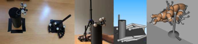
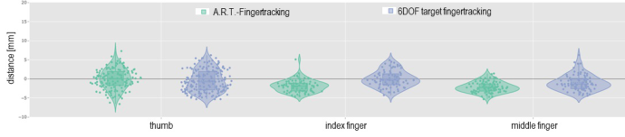
Study 2 includes 5 subjects, which had the task to grab and move two different cylinders (diameter d = 50 mm and d = 10 mm) with their fin- gertips. We captured the movements in 10 sessions with both technologies: 5 sessions used the ART-FTM and 5 sessions used the finger tracking based on our 6DOF targets. For each session we calibrated the tracking method accordingly (choosing the static calibration for the 6DOF targets). Each ses- sion consisted of two trials, differentiated by the magnitude of applied force (trial 1: “touch as gentle as possible”, trial 2: “touch as strong as possible”). Within each trial the subject had to move both cylinders with the right hand, using two technics: thumb and index finger, as well as thumb and middle fin- ger. Afterwards the subject should touch the thumb with the index finger and the thumb with the middle finger. The cylinders were built as 3D-print and tracked as 6DOF targets. To calculate the accuracy we used the mean distance between the lateral surface of the cylinder and the fingertips during the move- ment of the cylinders. The expected value is 0 mm reduced by the unknown soft tissue deformation. To analyze the accuracy and precision we use violin plots for each finger and the RMSE. An Analysis of Variance with the Tukey post-hoc test was used to calculate significance. Both studies where done in the same setup using a table surrounded by 12 ARTTRACK5 cameras. Figure 4 shows some impressions.
Figure 4: From left to right: cylinder (d= 50 mm and d = 10 mm), starting position, visualization of the ART-FTM, visualization of our 6DOF target finger tracking.
RESULTS
To compare the anthropometry of the ART-FTM with our 6DOF tracking we can only use the width and thickness of the fingertip, simply because the ART-FTM measures only one radius of the fingertip (Table 1). The ART- FTM tends to create larger fingertips compared to measurements using the anthropometer. The tip tends to be 2.64 mm wider and 6.1 mm thicker, within the given Limits of Agreement (LoA). The static landmark calibration results in 1.67 mm smaller and 1.28 mm thinner fingertips, within the given LoA. Over all joints and fingers the landmark calibration tends to be more accurate with only 0.53 mm or 0.22 mm differences.
Table 1. Comparing the anthropometry measurement using the Bland-Altman method.
Table available in the original PDF paper.
Static landmark calibration –
ART-FTM – anthropometer
anthropometer LoA mean LoA LoA mean LoA
FINGERTIP (thumb, index finger and middle finger) width −2.63 mm 2.64 mm 7.92 mm −6.04 mm −1.67 mm 2.7 mm thickness 2.23 mm 6.1 mm 9.96 mm −4.93 mm −1.28 mm 2.37 mm
OVERALL (including DIP, PIP, MCP and CMC for all fingers) width −5.6 mm 0.22 mm 6.05 mm thickness −4.84 mm 0.53 mm 5.9 mm
For the phalange length the ART-FTM uses a fixed ratio (Littler, 1973) and even tends to change the length of the whole finger during measure- ments. This ratio is discussed in the literature, which should not be part of this work. Nevertheless it is interesting to know the reliability of our static landmark calibration. We therefor calculated the TRV for the length, width and thickness (Table 2). Looking at the phalange length, repeated calibrati- ons result in differences less than 6.9% for 75% of all measurements. The differences for width and thickness are higher, because of smaller absolute values.
Table 2. Test-Retest Variability (TRV) of the static landmark calibration.
Table available in the original PDF paper.
length width thickness
3. Quantile 6.9% 9.2% 9.8% median 3.9% 4.8% 5.4%
To represent the reliability of the joint estimation via landmarks, we calcu- lated a mean joint position and the distance to each measurement (Figure 5). The RMSE for all MCP joints is nearly identical with 1.7 mm. The CMC of the thumb is more difficult to measure, represented with a RMSE of 2.6 mm. Nevertheless taking the maximum distance of 4.4 mm and knowing that a distance could occur in all spatial directions, two measurements of the thumb CMC are always within a sphere smaller than 10 mm diameter. This seems acceptable, so we use the landmark method as reference to compare the ART-FTM and the dynamic CoR calculation.
Figure 5: Violin plots for the distance of different joint calibrations using the static landmark method.
Precision of Marker-Based Finger Tracking for Broad Biomechanical Studies 85
The dynamic calibration for each MCP joint created a mean distance of 5.5 mm. The ART-FTM was comparable with 6.8 mm mean distance. But for the CMC joint of the thumb the results are simply not acceptable for both methods, given the more than 30 mm mean distance. Figure 6 shows an example with the hand visualization of the ART-FTM. The dark green spheres (d = 10 mm) on the left site represent the measured landmarks. The brighter green spheres represent the calculated joint position. The red spheres represent the calibrated ART-FTM joints (CMC of the thumb, MCP of index finger and middle finger) and the blue sphere represents the calculated CoR of the dynamic calibration for the CMC joint. The ART-FTM CMC joints (red) tend to move to the dorsal direction of the palm, depending on a specific calibration posture. The dynamic CoR calibration joint (blue) tend to move towards the thumb MCP joint, simply because it is not possible to fix the joint movement during the calibration (even using bandaging). As result we stick with the static landmark calibration.
Figure 6: Wrong position of the CMC joint from two perspectives.
Before we start to analyze study 2, we needed to delete measurement with tracking problems. Unfortunately the ART-FTM could not capture the fingers constantly. As a result we removed 21% of our data. Only 23.5% of our trials could be captured without loose of sight of any of the fingers. This was due to the reduced visibility of the active IR-markers in the fingertips, with an angle between 120° and 150° to emit the light. In contrast the 6DOF target tracking worked fine, capturing more than 90% of our trials without any loose. Never the less we needed to delete 8.2% of our data due to failed calibration and additional 9% due to loose of sight of targets.
The results for study 2 are shown in figure 7. Both methods represent the fingertips very accurate with a median penetration depth of the cylinder sur- face of 1.45 mm (ART-FTM) or 0.8 mm (6DOF target finger tracking). The precision is comparable as well with RMSE of 2.59 mm for both methods. These results are a bit of a surprise considering, that the thickness of the fingers influences the distance to the cylinder surface. And the results sho- wed, that the thickness is clearly better represented using the static calibration
Figure 7: Distance between the fingertips and the lateral surface of the cylinder.
strategy. Both systems surpass the accuracy and precision of the leap motion controller (Valentin and Pezotti, 2017), but seem to be even or less accurate compared to single marker tracking (Cerveri et al., 2007). Nevertheless, both systems detected significant (p < 0.05) differences between trials using a “gen- tle touch” and trials using a “strong touch”. While the ART-FTM measured a mean difference of 0.13 mm, the 6DOF tracking measured a difference of 0.77 mm.
CONCLUSION
Overall we included two finger tracking measurement methods. The benefits of the 6DOF tracking include a better representation of the anthropome- try and the joint positions, as well as lesser loose of sights. This will allow the execution of experiments regarding biomechanical stress and strain. The ART-FTM shows comparable accuracy of the fingertips and a faster calibra- tion routine. Thus, we will use it for pretests or finger tracking without the intent of biomechanical analysis.
REFERENCES
Bland, J. M., & Altman, D. (1986). Statistical methods for assessing agreement between two methods of clinical measurement. The lancet, 327(8476), 307–310. Bland, J. M., & Altman, D. G. (1999). Measuring agreement in method comparison
studies. Statistical methods in medical research, 8(2), 135-160. Cerveri, P., Lopomo, N., Pedotti, A., & Ferrigno, G. (2005). Derivation of centers and axes of rotation for wrist and fingers in a hand kinematic model: methods and reliability results. Annals of biomedical Engineering, 33(3), 402–412. Cerveri, P., De Momi, E., Lopomo, N., Baud-Bovy, G., Barros, R. M. L., & Ferrigno,
G. (2007). Finger kinematic modeling and real-time hand motion estimation. Annals of biomedical engineering, 35(11), 1989–2002. Ehrig, R. M., Taylor, W. R., Duda, G. N., & Heller, M. O. (2006). A survey of formal methods for determining the centre of rotation of ball joints. Journal of biomechanics, 39(15), 2798–2809. Hillebrand, G., Bauer, M., Achatz, K., Klinker, G., & Oferl, A. (2006, September).
Inverse kinematic infrared optical finger tracking. In Proceedings of the 9th International Conference on Humans and Computers (HC 2006), Aizu, Japan (pp. 6–9). Houston, A., Walters, V., Corbett, T., & Coppack, R. (2021). Evaluation of a multisensor Leap Motion setup for biomechanical motion capture of the hand. Journal of Biomechanics, 127, 110713. Kaiser, A., & Bullinger, A. C. (2020). Precision of Human Movement in the Vir-
tual Reach Envelope-Measurement of Static and Dynamic Precision Depending on Different Movement Speeds. In DHM2020 (pp. 145–155). IOS Press. Littler, J. W. (1973). On the adaptability of man’s hand (with reference to the equiangular curve). Hand, 5(3), 187–191.
Precision of Marker-Based Finger Tracking for Broad Biomechanical Studies 87
Rüffert, D.; Mühlstedt, J., Bullinger, AC. (2015). Ergonomie im Griff?. Bewegungsstudie zu Präzision im Greifraum. In Gesellschaft für Arbeitswissenschaft e.V., editors. Tagungsband GfA-Frühjahrskongress. Verantwortung für die Arbeit der Zukunft. Sancho-Bru, J. L., Pérez-González, A., Mora, M. C., León, B. E., Vergara, M.,
Iserte, J. L., ... & Morales, A. (2011). Towards a realistic and self-contained biomechanical model of the hand. In Theoretical biomechanics. IntechOpen. Valentini, P. P., & Pezzuti, E. (2017). Accuracy in fingertip tracking using leap motion controller for interactive virtual applications. International Journal on Interactive Design and Manufacturing (IJIDeM), 11(3), 641–650.
LISTED IN THE AHFE DIGITAL BOOKSTORE CATALOGUE
Explore the complete digital volume
Digital Human Modeling and Applied Optimization
Read this individual research paper free through the original publisher, or explore the full digital proceedings book.
ISBN 978-1-958651-22-3
Explore this ISBN in the AHFE Bookstore ↗Listed in the July 2026 bookstore catalogue; search by ISBN to confirm current availability · Digital book purchase optional