Jeremy Mohon, Casey Kovesdi (2022). Demonstrating the Value of 3D Models to Support Large-Scale Digital Modifications at Nuclear Power Plants. In: Digital Human Modeling and Applied Optimization. AHFE Open Access, vol. 46, pp. 8–15. https://doi.org/10.54941/ahfe1001894
The existing nuclear power plants (NPPs) in the United States (U.S.) are important for creating safe and reliable carbon free electricity for now and in the future. Many NPPs are currently in the process of extending their operating licenses for continued generation. Extending the lifespan of these plants provide an opportunity to modernize their operating model by introducing new technologies that reduce operations and maintenance costs. Many businesses have introduced new technologies to help with reducing costs; however, introduction of new technology has created situations where processes were less efficient. Hence, human factors evaluations are needed to help ensure that new technologies can integrate safely and reliably with current operations. Standards and guidelines for applying human factors in NPP modernization are available from the Nuclear Regulatory Commission, (NRC) , the Electric Power Research Institute (EPRI), Institute of Nuclear Power Operations (INPO), among others. One such method used in human factors to support modernization is the use of three-dimensional (3D) modeling that enables visualization and anthropometric evaluation. That is, anthropometric data including reach, sight, and distance are important human factors considerations to ensure that all interactions can be completed safely and effectively by personnel interacting with work processes and operations.This report discusses the importance of applying 3D modeling techniques within the context of human factors evaluation for large scale digital NPP modifications. 3D modeling is one area where human factors engineering can be applied when modifying or adding new technology into control room operations. Models of the control room can be created in 3D modeling tools to present visualizations of modifications or new technologies being introduced into the control room. Available software tools such as Trimble Sketchup and Control Room Engineering Advanced Toolkit Environment (CREATE) (developed by the Institute for Energy Technology) can be used to evaluate anthropometric considerations like sight lines, readability, distance of controls, and other related information to represent changes prior to implementing new modifications or technologies in a control room. These tools enable early human factors input that can drive effective decisions making later in the development process. The CREATE tool has been designed to include guidance and information from the NRC (i.e., NUREG-0700) directly into its operating system allowing for human factors guidance to be automatically applied when creating 3D visualization of a control room. 3D modeling can also be used as a visualization tool to describe and report changes to key stakeholders very early on, prior to implementing changes in a control room. This report will summarize recent work performed in collaboration with a partnering utility that generates lessons learned when using 3D modeling for control room modernization.
The existing nuclear power plants (NPPs) in the United States (U.S.) are important for producing safe and reliable carbon-free electricity for now and in the future. Many NPPs are currently in the process of extending their operating licenses for continued generation. Extending the lifespan of these plants provide an opportunity to modernize their operating model by intro- ducing new technologies that help to reduce operations and maintenance costs.
Demonstrating the Value of 3D Models to Support Large-Scale Digital Modifications 9
established guidelines and allows for visual presentation of the 3D model to various stakeholders in the project. Thus, critical design decisions can be made in nearly real-time through facilitated discussions and ‘what if’ evalu- ations with the impacted changes. This is accomplished since 3D modeling techniques provide visualization of proposed changes without having to cre- ate physical mockups. Human factors guidance can be incorporated into the 3D model to help ensure that human factors requirements are being met by using multiple guidance resources from the Nuclear Regulatory Commis- sion, (NRC) and the Electric Power Research Institute (EPRI), among other sources. Specifically, guidance for workplace design and workstations using anthropometric data and other information can be used in the 3D model to support modernization activities in NPPs.
This work discusses the value of applying 3D modeling techniques within the context of HF/E for large scale digital NPP modifications. 3D mode- ling is one area where HF/E can be applied when modifying or adding new technology into control room operations. Models of the control room can be created in 3D modeling tools to present visualizations of modifications or new technologies being introduced into the control room. Commercially available software tools such as Trimble Sketchup and ergonomic software extensions, CGM Ergo Loader, using Digital Human Models (DHM) can be readily used to evaluate anthropometric considerations like sight lines, reada- bility, distance of controls, and other related information to represent changes prior to implementing new modifications or technologies in a control room. These tools enable early human factors input that can drive effective deci- sions making later in the development process. Applying 3D modeling with DHM and HF/E guidance concurrently can also be used as a visualization tool to describe and report changes to key stakeholders very early on, prior to implementing changes in a control room. This paper summarizes recent work performed in collaboration with a partnering utility that generated les- sons learned when using 3D modeling and HF/E Guidance for control room modernization.
The Role of Human Factors Guidance in HF/E The NRC and EPRI provide guidance on performing HF/E for control rooms and design modifications. The responsibility of the NRC is to complete and review HF/E as a part of safety analysis reports for NPPs (Nuclear Regulatory Commission, 2012). The review process by the NRC includes reviewing guidance from the Human Factors Engineering Program Review Model (NUREG 0711 Revision 3) which includes detailed design review pro- cedures. Another standard and guideline used along with the NUREG 0711 Revision 3 is the NUREG 0700 Revision 2 and 3 which contains human factors design guidelines that can serve as a technical basis for style guide development, as well as provide verification criteria for use during regulatory review as part of the NPP standard review plan (NUREG 0800). Depending on the age of the NPP, previous human factors engineering commitments to NUREG-0700 may reference different versions that reflected the time in which the plant was originally licensed. Further, NPPs undergoing stepwise modernizations may have committed to an interim revision of NUREG-0700
10 Mohon and Kovesdi
such as Revision 2 and not Revision 3, published in 2020. The guidance betw- een revisions may differ when evaluating the workplace and workstations. Nonetheless, these different revisions can each be included in the 3D models for evaluation. The next section addresses how 3D modeling is used with HF/E. The next section addresses how 3D modeling is used with HF/E.
Development and Use of 3D Models There are several commercially available tools for 3D model development. One such tool is called Trimble SketchUp. The software can be used to create 3D models and allows importing data such as photos, AutoCAD files, 3DS files, and other files to be added into the model. A DHM software extension available in Trimble Sketchup called CGM Ergo Loader was used to represent 5th percentile female and 95th percentile males to help identify HF/E issues during evaluation of NUREG 0700 and other HF/E guidelines. Drawing and images of the NPP can be used to inform the design of the model. Human factors professionals must verify that the scaling of the model is correct using drawings of the room and layout. Human factors professionals must consi- der that the dimensions of the model are scaled correctly while also ensuring accurate measurements between items in the 3D model. Images of the NPP control room equipment can be used as input in designing the model. Human Factors professionals add these images to create a realistic visual representa- tion of NPP control rooms. Changes and modifications that are discussed in meetings with utilities can then be visually represented by modifying the geometry and images to present the new state of the control rooms being modernized.
When the model has been developed, it can support early evaluations of the proposed changes or modifications. For many years human factors has been introduced towards the end of projects instead of being used in the very start (Gustavsen & Louka, 2012). Introducing HF/E early in the project through 3D modeling allows for early visualizations of changes and modifi- cations in control rooms to help save costs and present information early on to stakeholders involved in the project. 3D models help to provide visuals of information and are iterative allowing for additional verification and valida- tion to be completed on early design concepts. Having 3D models available allows human factors issues to be addressed early in the design versus having to address human issues later in the design leading to increased costs and time to evaluate the design. HF/E guidance from the NRC (NUREG 0700) and EPRI are evaluated using the 3D models to provide visualizations of the control room modifications and address potential human factors issues.
Demonstrating the Value of 3D Modeling This section provides examples of some HF/E guidelines used to create visu- alizations of large-scale control room modernization efforts for partnering utilities. Guidelines from NUREG 0700, 0711, and EPRI’s 2015 Technical Report on Human Factors Guidance for Control Rooms are included in the examples for human factors issues to be identified early in the design when using 3D modeling with DHMs and HF/E guidance.
Demonstrating the Value of 3D Models to Support Large-Scale Digital Modifications 11
Distance and Measurements 3D modeling provides early visualization of the environment planned for large scale digital modernization by scaling the model to the dimensions of the control room. Scaling of 3D models is achieved by having a layout and documentation for equipment and fixtures in the control room dimensions. Human factors professionals interpret the information and check multiple angles of workstations, operations area, and other equipment to confirm that the 3D model is visually accurate representation of the control room area. One area of concern is if the 3D model is not scaled properly between equi- pment and workstations leading to human factors issues occurring in later steps of the project. One way we have used to prevent scaling issues is having a team of at least two human factor professionals where one completes the model and verifies measurements, and another human factors professional checks and verifies the 3D model is visually accurate as a peer review. For an additional verification of scaling in the 3D model we have presented the model to engineering and operations during meeting with utilities to confirm that the 3D model is accurate. The next section will discuss how workstation design is used in 3D modeling.
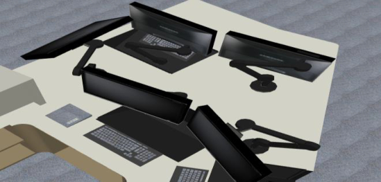
Workstation Design 3D modeling of workstation design is useful for identifying what changes and modifications will added such as: new HSI’s, modifications to workstati- ons, or replacing workstations as part of the large-scale modernization effort. 3D model visualizations of workstation design are evaluated by identifying human issues such as user safety when adding new modifications to worksta- tions. For example, adding in monitors with movable arms that may cause pinch points to users or having sharp edges or corners on new workstations. Figure 1. Shows a user safety example of multiple monitors mounted on a desk with possible pinch points. This potential human factor issue can be identified early in modernization efforts to prevent pinch points from occur- ring in workstation designs. In addition, available space on the workstations can be visually represented to show if space is available for adding additio- nal equipment to the computer workstations that is necessary for operators to complete their tasks. The next section will discuss the value of 3D modeling in addressing anthropometric considerations.
Figure 1: Example of Computer Displays on Rotating Arms.
12 Mohon and Kovesdi
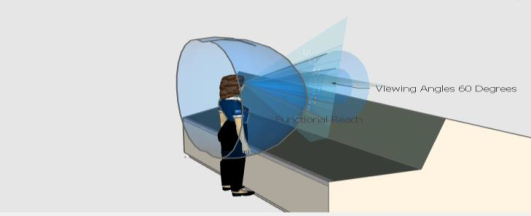
Anthropometric Considerations: Reach, Viewing Angle, and Sight Lines Anthropometric considerations are important to the design of workstati- ons and the workplace. The use of DHM in 3D Models has been used in many industries to evaluate ergonomics and HF/E earlier in the design to help reduce late design modification efforts (Demeriel & Duffy, 2007). 3D models using DHM⣙s can be used to evaluate reach, viewing angle, and sight line considerations of the operator. These evaluations use anthropo- metric data of population stereotypes from sources like MIL-STD-1472G and NUREG-0700 that account for functional reach, horizontal and verti- cal view angles, and eye heights of of personnel working in the control room, based on population extremes from the 95th percentile male and 5th percen- tile female population. DHM representations can be used to represent these ranges to evalute considerations like functional reach when interacting with controls. Seated or Standing workstations can be evaluated using 3D models and human factors guidance to verify that functional reach of controls is not out of reach for personnel operating the controls. HF/E of height of equi- pment can also be evaluated to identify design adequacies that are present due to the placement of equipment if blocking the view of critical indications that must be monitored.
Figure 2 highlights an example of a 5th percentile female with a functio- nal reach envelope and viewing angle represented when interacting with a standing workstation. The circular cone shape view represents the functio- nal reach, and the 60-degree horizontal and vertical viewing angles from the current position. Using DHM representations of smallest to largest person- nel heights helps to find where design inadequacies may occur such as having controls too far away to operate or having critical information out of sight or blocked from view due to the height and placement of equipment.
Figure 2: Standing workstation functional reach and 60-degree viewing angles.
Sight lines are also used for evaluating displays that require frequent or continuous monitoring and can be represented in the 3D model from human factors design guidelines in NUREG 0700 regarding arrangement of displays concerning horizontal and vertical viewing areas. For instance, NUREG-0700 Revision 3 offers new guidance in the design of computer- based workstations that require seated work. Performing HF/E on sight lines
Demonstrating the Value of 3D Models to Support Large-Scale Digital Modifications 13
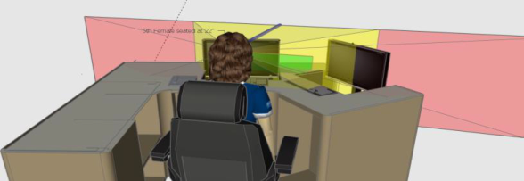
is beneficial to prevent design adequacies if monitors are placed where they block the view of frequently monitored information or are not within the pro- per viewing area for seated work. Figure 3 illustrates a 5th percentile female seated, with the chair being 22 inches from the floor, at a seated workstation.
Figure 3: 3D representation of horizontal viewing area of computer monitors displays.
The viewing angles are represented by the colored cones. The green cone is represented as the preferred normal line of sight (LOS). This is indicated using NUREG-0700 Revision 3 guidelines 11.3.1.2-1 (Vertical Viewing Angle) and 11.3.1.2-2 (Horizontal Viewing Angle) to represent the preferred placement of critical task-related information. The cone her indicates a position of minus 15 to minus 25 degrees below the LOS and 15 to the left and right (horizon- tal) to the LOS. The yellow cone represents minimal guidance for placement of displays when head rotation is not acceptable when performing a task. This cone follows the same guidance in NUREG-0700 and is represented as being 0 degrees to minus 45 degrees below the LOS and 35 degrees left and right (horizontal) of the LOS. Where read rotation is acceptable, the red cone indications the same vertical LOS as the yellow cone, but with horizontal viewing at 60 degrees left and right of the LOS. The next section discusses the use 3D modeling to elicit stakeholder feedback.
Eliciting Early Feedback of Proposed Modifications Beyond the use of DHM, 3D models can be used to communicate to stakeh- olders early in the design process to identify important changes to the control room that may impact the concept of operations. Future digital modificati- ons can be visually represented in the 3D models in near real time as new information or changes are identified such as removing manual controls and installing computer monitors, overview and touchscreen displays for control room operations. That is, human factors professionals can work with stakeh- olders and design team to make changes to the 3D model in real-time to help address questions or concerns such as display size or location of displays, and other pertinent considerations that may impact the concept of operati- ons. For instance, human factors professionals can work with the design team to address ideal placement and sizing of monitors for digital modifications in the main control room by performing ‘what if’ assessments with operati- ons, engineering, and project management to identify the ideal placement and size of monitors to support safe and reliable operation with the new digital
14 Mohon and Kovesdi
system. These assessments can thus determine whether a large size overview display would be able to fit in the space and whether its placement has any negative impact on task performance. Having the ability to make changes as needed in real-time helps utilities to answer questions on what space they have available for equipment and displays.
FINAL REMARKS 3D modeling is a useful tool to represent early designs in large scale moderni- zation project efforts and can help prevent human issues early in the design. Inclusion of anthropometric information, sight lines, workstation HF/E, and real time changes from DHMs and 3D modeling are helpful to create visuali- zations of the control room to find human issues. There are some limitations when using 3D modeling such as having inaccurate measurements or having multiple iterations. Despite the limitations, 3D modeling is a useful tool to perform V&V early in modernization efforts to help reduce costs and pre- sent visuals to stakeholders early in the process to help answer questions and perform HF/E early on in the large-scale modernization project. Future work will focus on incorporating 3D models from the SketchUp 3D mode- ling tool into the Control Room Engineering Advanced Toolkit Environment (CREATE) (developed by the Institute for Energy Technology) (Louka, 2021) software tool. The CREATE tool can be used to evaluate anthropometric con- siderations like sight lines, readability, distance of controls, and other related information to represent changes prior to implementing new modifications or technologies in a control room using DHMs and HF/E guidance.
ACKNOWLEDGMENT
This work of authorship was prepared as an account of work sponsored by Idaho National Laboratory (under Contract DE-AC07-05ID14517), an age- ncy of the U.S. Government. Neither the U.S. Government, nor any agency thereof, nor any of their employees makes any warranty, express or implied, or assumes any legal liability or responsibility for the accuracy, completeness, or usefulness of any information, apparatus, product, or process disclosed, or represents that its use would not infringe privately owned rights.
REFERENCES
Demirel, H.O. & Duffy, V.G. (2007). Applications of Digital Human Modeling in Industry. In: Duffy, V.G. (eds) Digital Human Modeling. ICDHM 2007. Lecture Notes in Computer Science, vol 4561. Springer, Berlin, Heidelberg. https://doi.org/10.1007/978-3-540-73321-8_93 EPRI (2015). “Human Factors Guidance for Control Room and Digital Human-
System Interface Design and Modification.” EPRI 3002004310, Electric Power Research Institute. Gustavsen, M. & Louka, M. (2012): Supporting Human factors engineering design review activities using virtual control room mockups. Conference: 8th Internati- onal Topical Meeting on Nuclear Plant Instrumentation, Controls, and Human Machine Interface Technology (NPIC&HMIT 2012) At: San Diego, CA.
Demonstrating the Value of 3D Models to Support Large-Scale Digital Modifications 15
Louka, M. (2021). HVRC CREATE. Institute for Energy Technology. https://ife.no /en/Service/hvrc-create/ U.S. Department of Defense Department of Defense Design Criteria Standard (2012):
Human Engineering (MIL-STD-1472G). Washington, DC: U.S. Department of Defense. (2012). U.S. Nuclear Regulatory Commission (1981). Guidelines for Control Room Design Reviews (NUREG-0700). Washington, DC: U.S. Nuclear Regulatory Commission U.S. Nuclear Regulatory Commission. (2012): “Human Factors Engineering Pro-
Read this individual research paper free through the original publisher, or explore the full digital proceedings book.
ISBN 978-1-958651-22-3
Explore this ISBN in the AHFE Bookstore ↗Listed in the July 2026 bookstore catalogue; search by ISBN to confirm current availability · Digital book purchase optional