Arcadio Reyes-Lecuonaa, Luis Molina-Tancoa, Daniel González-Toledoa, Susana Floresb, Eva Frutosb, Harshada Patelc, Robert Houghtonc (2020). Design, Maintenance and Refurbishment of Turbines in a Collaborative Environment. In: Advances in Social and Organizational Factors. AHFE Open Access, vol. 9. https://doi.org/10.54941/ahfe100319
1 University of Malaga, Departamento de Tecnología Electrónica, Campus de Teatinos, s/n, Málaga, 29071, Spain b Tecnatom S.A., Avda. de Montes de Oca 1 28703, San Sebastián de los Reyes, Spain ↗
2 Tecnatom S.A. Avda. de Montes de Oca 1 28703, San Sebastián de los Reyes, Spain ↗
3 University of Nottingham, Human Factors Research Group, Innovative Technology Research Centre, Dept. of Mechanical, Materials and Manufacturing Engineering, University Park, Nottingham, NG7 2RD, United Kingdom ↗
In this paper, a conceptual prototype of a collaborative tool for supporting decision making in the context of power plants maintenance is presented. The context of this industrial problem together with an analysis of the need for such a tool is also described. Then, a use case analysis is performed, as a conceptual specification of this tool. This conceptual prototype was evaluated using the cognitive walkthrough technique and the results of that evaluation process are also presented here.
Inspection of turbines in Fossil and Nuclear Power Plants presents some challenging issues in balancing different needs for representation and the extent to which business concerns permit common representations can be shared. On the one hand, the results of these inspections have to be communicated in the most accurate way, especially if defects have been detected, to the power plant, to the engineers who have to evaluate the results and the company that has to carry out the repair. On the other hand, this information could also be shared with the companies in the supply chain that designed, supervised and manufactured the turbine so that they can analyse the problem, propose a definitive solution and even modify the design to avoid these kinds of problems in future designs.
The Use-it-Wisely (UiW) project funded by the European Union within the 7th Framework Program, is tackling these issues by investigating a new business model that implements continuous product-service adaptation. An adaptation platform will be developed, including a multi-disciplinary actor-product-service system model, an adaptation mechanism based on the knowledge and skills of all actors involved in the system and an interactive collaborative distributed environment. One of the industrial cases where these ideas will be demonstrated is focused on the decision-making process after the inspection of a turbine in a power plant.
Tecnatom is a Spanish company that carries out routine turbine inspections in FPPs (Fossil Power Plants) and NPPs (Nuclear Power Plants across more than fifty gas and steam turbines from different technologies and manufacturers. The results of these inspections have to be transmitted in the most efficient way, especially if defects have been detected, to the power plant, to engineering to evaluate the results (sometimes Tecnatom, other times the turbine
Edited by T. Ahram, W. Karwowski and T. Marek designer). They are sent to the company that has to carry out the repair. This information also has to be shared with the companies that designed, supervised and manufactured the turbine so that they analyse the problem, propose a definitive solution and also modify the design to avoid similar problems in future designs.
Apart from the inspections, these turbines could have some kind of design modification due to different plant requirements: increase of the electric power generated by the plant, avoid specific degradation mechanisms, such as magnetite deposition, etc. Depending on the reason for the modification, including the percentage of power increase compared to the original one, the whole turbine or merely a subset of it may have to be replaced. These improvements may delay or even avoid whole-turbine replacement, and consequently reduce overall costs in terms of time, materials and lost production.
In these cases, Tecnatom’s interest is centred in reviewing the design before it has been applied in order to guarantee that the new or improved parts could be inspected as well as the requirements of such inspection. Moreover, Tecnatom sometimes provides advice about the feasibility of the change from the point of view of maintainability. In all those cases the communication between the different actors: power plant or final user, the turbine designer, the manufacturer, the companies that carry out the maintenance, the engineering firm that evaluates the results of the inspection, the engineering company in charge of the repair/modification, and so on, are both very important and somewhat challenging.
During the last 15 years, Tecnatom has internally developed software tools to manage the inspection and testing plan as well as the subsequent results of such inspections. These tools are successfully implemented in several Spanish FPPs, coal fired and combined cycle plants. Recently, our end users (mainly plant owners) have identified a requirement for a more reliable tool which provides value-added services in collaborative environments for supporting the decision making process along the life cycle, from designers to engineers.
Therefore, the specific objectives in the updating of these tools to generate an innovative and smarter one, can be broken down into the following requirements:
The provision of interactive 3D drawings in which the results of the inspections, the modifications/repairs carried out could be introduced. The application should be compatible with the most popular formats of spreadsheet, photography and CAD systems: .xls, .jpg, .dwg, .igs, .stp;
The availability of 3D part library (e.g., screws, blades of different designs) in order to check the results of the design modifications, selecting the best proposal, before it is put into practice. In this aspect, designers don’t usually take into account accessibility issues to maintenance and inspection;
The availability of inverse engineering tools to recalculate stress, strains, etc. The application should be able to easily export data to FEM (Finite Element Modeling) tools such as ANSYS (compatible formats: IGES or STEP).
Connection with simulation tools (such as those associated with Computational Fluid Dynamics) in order to know how the operation affects existing defects in the turbine.
In this case, all actors have different knowledge and different goals. The different stakeholders may have difficulties understanding the situation in the same way and may find it difficult to communicate their own view. Actors may make different proposals that the plant has to evaluate. It is very hard to make comparisons with previous inspection data and while decisions get made it is not clear that all outcomes have been equally or fairly evaluated. As a result, it has been noted that when a problem is detected in a turbine, the decision making process for solving it, takes a long time, since many actors are involved and the available information is based on paper reports and 2D drawings.
We envisage UiW aiding in the following example scenario: Tecnatom, as the inspection company, has detected a problem in a turbine’s blade (e.g. a crack in the foot). All the results of the inspection are entered in the tool (including pictures) through pre-defined templates and are added to the common model where all the information is stored and managed. There are four possible decisions to be taken:
1. Leave the blade as it is and reschedule subsequent inspections for shorter periods (e.g. every 2 years, instead of 8);
Edited by T. Ahram, W. Karwowski and T. Marek
2. Repair the blade and reschedule inspections, increasing the inspection scope (e.g. in 4 years, instead of 8; the inspection time is increasing up to 3 days.);
3. Substitute the blade for a new one and reschedule inspection (e.g. in 4 years, instead of 8);
4. Redesign the blades considering the information collected from past inspections, taking advantage of this change to improve design for vibration reduction or turbine efficiency increase.
In order to take the optimum decision, several actors have to discuss the situation: the owner of the turbine (Power plant), the designer, the manufacturer (involved in case of redesign), the inspection company and the engineering firm. All these actors have access to the common model which includes 3D models, annotations, documents, etc. (maybe it could require different user interfaces depending on the user profile). All actors can discuss on the model, add arguments and decide which the best option is, considering economic and technical issues.
The innovative and refurbished tool proposed will provide increased added-value to a wide range of users since it will facilitate the sharing of this information through a collaborative network while ensuring simplicity in the data access. This will enable seamless communication among all actors and also will lead to a reduction of costs by minimizing set-up and ramp-up times.
Within the UiW project, tools will be developed for sharing a 3D visualization of parts where the inspection has taken place. This visualization system has to be linked to a database containing inputs from the maintenance companies, the manufacturers, the plant operational experience, and so on. In addition to these tools, some collaborative methods will be developed. The goal is for the stakeholder team to have a set of linked visualizations based around a common model that everyone can understand This paper will present the results of the first iteration of the project, where a conceptual prototype of tools and methods has been evaluated.
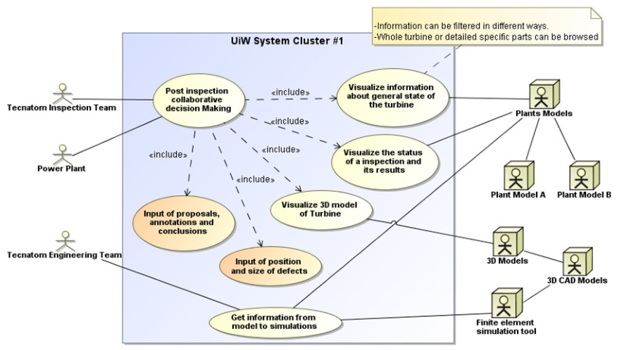
DESIGN PROPOSAL All the models in the present paper were generated through an iterative participatory process in which industrial experts in the cluster have challenged, corrected and validated these models during online meetings. With all the information collected from the company, a functional model describing the use cases was produced. A functional diagram approach based on SysML syntax (Object Management Group, 2012) for use case modelling has been used, where the functionalities required by actors are depicted as Use Cases. In addition to this process were produced dynamic models for relevant dynamic problems.
Uses Cases Description This section describes a use-case model of a system which would solve the problem of information flow among the actors involved in the decision processes within turbine inspection and maintenance. The system that is expected to be developed would integrate a virtualized common system model that would provide mechanisms for information sharing and decision support.
The system described would act as complement to the virtualized model of every plant, supporting the existing applications in Tecnatom to provide 3D visualization and information sharing to support decision making.
Actors
Tecnatom Inspection Team: This actor represents the team of Tecnatom in charge of planning inspections, execute them and inform about these results.
Tecnatom Engineering Team: This actor represents the team of Tecnatom in charge of preparing and executing simulations, analysing the results and introducing them in the model.
Power Plant: This actor represents the technical staff or management of the company that owns the power plant, or its subcontractors, i.e. Maintenance Team and Engineering.
Edited by T. Ahram, W. Karwowski and T. Marek
Plant Models: This actor represents the databases (DBs) that contain the model of the whole Power Plant. Only the part of that model representing the turbines and associated information is of interest for the UiW system.
3D Models: This actor represents the Databases that contain the 3D geometry of the different turbines.
Finite element simulations tool: This actor represents the tools those are used by the actor Tecnatom Engineering Team to execute the simulations.
Use Cases Use-Case: Post Inspection collaborative decision making
When a defect is discovered during the inspection of a turbine, a collaborative mechanism is started to give the actors the possibility to make different proposals to deal with this defect. Based on this proposal a discussion is started among the stakeholders to reach a consensus decision about which of the proposed solutions is best in terms of cost, risk of future failure and duration of power plant shutdown time.
Use-Case: Visualize information about general state of the Turbine The actors wish to visualize the current state of a turbine and its parts. The system gives the actors the possibility to navigate through the turbine model and have access to visualization of all the information stored in the model about the state of the turbine, including plans, technical parameters, simulation results, etc.
Use-Case: Visualize the status of an inspection and its results Using the system the actors navigate through the turbine model and are able to visualize the results of all the inspections realized in the past. They are also able to get information about one inspection in particular, its results and the state of the turbine after and before the inspection. The actors are also able to visualize all information of corrective maintenance that rose due the results of an inspection: repairs, replacements, etc.
Use-Case: Visualize 3D model of Turbine The system provides an advanced 3D visualization tool by which the 3D geometry of the turbine is linked to the virtual model to allow spatially situated visualization of the turbine´s maintenance history.
Use-Case: Input of proposals, annotations and conclusions1 When a defect is detected during an inspection different actions are possible. The system provides a tool to allow every actor to register their proposal or annotations to solve a defect or defects. Proposal will be registered in a standard format, including estimated cost, execution time, etc. In the same way, the system provides to the stakeholders a tool to document all the decision making process.
Use-Case: Get information of model to simulations If during an inspection a defect is found but a fix or a replacement are not possible, a simulation can be performed to predict the future behaviour of the turbine before reaching a decision. These simulations are done in external applications but based on the results of the inspection. The system provides a mechanism to export the geometrical results of the inspection in order to be imported in the simulation tools.
Use-Case: Input of position and size of defects1 When flaws are discovered, in an inspection, it is necessary to register their position and size into the model. In most of the cases if not possible to do this in an automatic way, so the actors have to be able to register the position and size of defects using a 3D graphic tool provide by the system.
Relationships The use-case Post Inspection collaborative decision making has an include relationship with these four other use-
1 The use-cases show here are the final and agreed-upon versions after the trial. See “Results” section. Social and Organizational Factors (2020)
Edited by T. Ahram, W. Karwowski and T. Marek cases: Visualize information about general state of the Turbine, Visualize the status of an inspection and its results, Visualize 3D model of Turbine, Input of proposals, annotations and conclusions and Input of position and size of defects.
These relationships show that the main use-case is that of helping in the post inspection decision making process. Analysis of this main activity results into five use-cases which are linked to external systems that provide information to support this process.
Figure 1. Diagram of the Use Case Model1
TRIAL This section describes the findings of a cognitive walkthrough (Wharton, 1994) that took place to verify that the system modelled met the expectations of all stakeholders, i.e., that all of them could perform their daily tasks with the system. Was detailed a plan that contained a description of the actors, a first draft of the interfaces, and a diagram that depicted the usual work flow for the various actors. All this, together with the use-case that implement the system and the APS (Actor Product Service) data model allowed us to check if the actors could deal with these situations by using the UiW system.
Methodologically, the cognitive walkthrough took the form of a meeting in which attendants took three different roles: Facilitators who understand how the system works (or will work); Experts who understand the tasks at hand and perform the role of a certain actor; Secretaries who are in charge of recording everything that happens during the meeting.
Prototype Description: Interfaces The draft versions of the application interfaces presented here will be used in the cognitive walkthrough. The first of these interfaces is intended for a situation in which the actors will likely have the priority to interact with model information through 3D visualization
1 The use-cases shows in different colour are those which were modified after the trial. See “Results” section. Social and Organizational Factors (2020)
Edited by T. Ahram, W. Karwowski and T. Marek Control Panel
Figure 2. Interface prototype. 3D Visualization Use-Case.
Figure available in the original PDF paper.
The second interface is intended for a situation in which the actors need to access all the information related to the area selected: descriptions, technical parameters, defects, reports, etc.
Figure 3. Interface prototype. Visualization of current status of the turbine
Figure available in the original PDF paper.
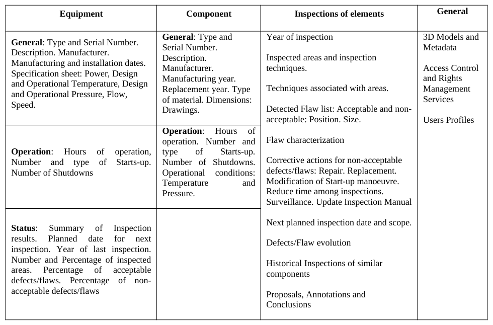
Prototype Description: System Model During the first design iteration, in addition to this functional analysis, a draft structure of any relevant information that the system has to store and manage in order to provide that functionalities was also identified. This draft structure is a first attempt to define the elements of the APS System Model which will be developed during the next steps.
Edited by T. Ahram, W. Karwowski and T. Marek
Table 1: Actor-Product-Service system Model
Verification Methods and Procedure The methodology of the verification trial will consist in following the usual decision-making process when the actors are confronted with a group of hypothetical defects found in the inspection of a turbine. The actors will try to do their job by means of the UIW system. This will take place in an in-person meeting that will take place in Tecnatom headquarters.
With this purpose a workflow of the decision-making process and the tasks that have to be resolved during the meeting by the actors were developed. This workflow summarizes the decision-making process that takes place among all stakeholders after inspection.
Next step was exhibit normal working situations involving different actors. The goal was then to confirm that each actor could do their job by means of the UIW system (with the use-cases set) and making use of the interfaces and data contained in the APS system model and following the workflow defined. Below are shown these tasks that the actors have to complete.
Task 1: When defects are found during an inspection, it becomes necessary to make a decision for action. The different stakeholders study the state of the turbine and the results of the inspections and are able to submit proposals to address the defect or defects found. Then a decision-making process begins.
Defect 1: Cracks inside inner cylinder in areas near nozzle chamber (High Temperature) Flow: Acceptable under the procedure? [Equation or mathematical symbol available in the original paper PDF] No Is operating with the defect feasible? [Equation or mathematical symbol available in the original paper PDF] Yes
Edited by T. Ahram, W. Karwowski and T. Marek
Defect 2: Mild erosion of stellite layer in later stages of blades (without affecting the integrity of the blade). Flow: Acceptable under the procedure? [Equation or mathematical symbol available in the original paper PDF] No Is operating with the defect feasible? [Equation or mathematical symbol available in the original paper PDF] No
Is repairing feasible? [Equation or mathematical symbol available in the original paper PDF] Yes
Defect 3: Indication for stress corrosion cracking in low-pressure turbine rotating blades. Flow: Acceptable under the procedure? [Equation or mathematical symbol available in the original paper PDF] No Is operating with the defect feasible? [Equation or mathematical symbol available in the original paper PDF] No Is repairing feasible? [Equation or mathematical symbol available in the original paper PDF] No
Is replacement possible? [Equation or mathematical symbol available in the original paper PDF] Yes Task 2: After an inspection various defects appear and simulations are needed. It is necessary to export geometric data of defects to the simulation tools.
Defect 4: Subsurface axial indication inside the rotor Flow: Acceptable under the procedure? [Equation or mathematical symbol available in the original paper PDF] No Is operating with the defect feasible? [Equation or mathematical symbol available in the original paper PDF] No Is repairing feasible? [Equation or mathematical symbol available in the original paper PDF] No Is replacing feasible? [Equation or mathematical symbol available in the original paper PDF] No FEM Simulation is performed
RESULTS
Revision of the APS System Model The trial started with a general revision of the APS system model. All the actors generally agree with what is going to be queried/accessed/displayed by the UiW system in every situation. However, in some cases it was necessary to qualify an element of the model, or even to add new elements to the model at request of some of the actors present.
Nevertheless, during the meeting it was discovered that many of the data required by the UiW system are at the moment not available: it is not considered in Tecnatom databases design or, more frequently, it is a non mandatory field and data are incomplete or user does not fill the information.
Revision of the interface prototypes The trial continued with the revision of the interface mockups. It was shared and clarified that there exist situations where what is more relevant for the actors is the 3D representation of the components, with highlighted, relevant information spatially situated over it. So, in these situations the 3D figure will have to be shown in the main window. Secondary associated information or resources will have to be shown in small side windows. Conversely, in other situations, what is more relevant is the information associated to an area or a component, and consequently it is that information which will have to be showed in the main window.
Cognitive walkthrough The cognitive walkthrough focused on Task 1 – Defect 1. All actors agreed that reaching a first decision on whether it is feasible to resume operation with a given defect is very complex. The expert playing the role of Tecnatom Inspection Team expressed that one of the main difficulties they face is making other actors understand the parameters of the defect, such as exact placement, size and others.
Placing and sizing the defects in the 3D geometry is a problem by itself. The experts agreed that, in general, it would be difficult to geometrically parameterize defects for the UiW system to represent these automatically, due to several reasons including the difficulty to recover information on reference coordinate-frames for components, and the near impossibility to measure the dimensions of some defects in real situations. Consequently, it was exposed that these parameters of position and dimension cannot always be stored in the current workflow. This would prevent the UiW
Edited by T. Ahram, W. Karwowski and T. Marek system to automatically represent defects in 3D to support the decision making process. The discussion led to the discovery that was necessary to redefined a use-case, was required from the UiW system that will allow the actors to place and size the defects manually over the 3D visualization, then the system will have to store these parameters that will be later recovered during the decision making processes.
During the walkthrough of the decision process it was also exposed that the system should not only allow the actors to register proposals, but also other annotations to document all the making decision process, with the aim of being able to know in the future what was proposed and what decision was taken and, more critical, the reason o f such decision.
Other general points were raised by the actors during the walkthrough, including:
The system will have to show/access all the information related with components and defects that will be stored in Tecnatom databases (GIPE system).
The system will have to link a defect that is shown over the 3D geometry with the images of the defect stored in Tecnatom databases.
The system will have to implement Access Control and Rights Management Services.
Lessons Learnt The impact of the trial can be summarized as follows:
The APS system model will have to be extended to include all the new requirements of information for components and defects. In Tecnatom Databases several levels are used to reach the smallest part of turbine, so that levels and related information to access a component/element should be detailed in APS model.
Tecnatom databases will have to be extended or new databases will have to be created to support the entire APS system model.
The use-case called Generate Proposal will have to be redefined to include the capacity to make annotations and document the decision-making process by the actors (for example Input of proposals, annotations and conclusions).
The ability to link images and 3D geometry will have to be included in the use-case Visualize the status of an inspection and its results.
The use-case Input of position and size of defects will have to be redefined to support the placing and sizing of the defects manually over the 3D visualization.
It will be necessary to implement profiles to the users of the system with the aim of implementing Access Control and Rights Management Services.
CONCLUSIONS
As a result of the trial, the conceptual prototype was pre-validated and system specification can go on further details. Building an application for visualizing technical information linked to specific locations in a 3D model of the inspected machine, and supporting collaborative work, can produce a great benefit, improving the quality of the decision making process. At least, this has been foreseen by the selected experts during the evaluation of this conceptual prototype.
The process of this evaluation, presented in this paper, has been a good way of validating the specified use cases to be developed. The cognitive walkthrough technique, usually used for interface evaluation, has been successfully used in this context, validating the proposed use cases and detecting some missing details.
Work will continue in the next months by writing a comprehensive set of requirements, which will guide
Edited by T. Ahram, W. Karwowski and T. Marek
development and evaluation in further technical trials.
REFERENCES
Object Management Group (2012), "OMG Systems Modeling Language (OMG SysML™). Version 1.3", Technical report available from www.sysml.org/docs/specs/. [Accessed Feb. 2014] Wharton, C., Rieman, J., Lewis, C. and Polson, P. (1994), "The Cognitive Walkthrough Method: A Practitioner's Guide", in
Usability Inspection Methods, Nielsen, J. and Macl, R.L. (Eds.), Wiley.
LISTED IN THE AHFE DIGITAL BOOKSTORE CATALOGUE
Explore the complete digital volume
Advances in Social and Organizational Factors
Read this individual research paper free through the original publisher, or explore the full digital proceedings book.
ISBN 978-1-4951-2102-9
Explore this ISBN in the AHFE Bookstore ↗Listed in the July 2026 bookstore catalogue; search by ISBN to confirm current availability · Digital book purchase optional