Sascha Hasenoehrl, Johannes Klotz, Patric Grauberger, Sebastian Zimprich, Niklas Bargen-Herzog, Jiahang Li, Marcus Geimer, Sven Matthiesen (2026). Methodical Approach for the Development of Multi Domain Testing Environments for Stable Operation Under Impulse Excitation. In: Human Interaction and Emerging Technologies (IHIET-FS 2026): Future Systems and Design Applications. AHFE Open Access, vol. 235, pp. 194–205. https://doi.org/10.54941/ahfe1007274
Repeated impulsive loads are critical for both structural integrity and human vibration exposure in power tools such as rotary hammers. Therefore, they need to be evaluated in a precise manner in order to consider them in design of these power tools. However, existing testing environments used to gain insights often fail to reproduce highly transient impact behaviour in a controllable and adjustable way, particularly when different physical domains, like mechanic and hydraulic, and workpiece properties must be represented. This paper proposes a five step, multi domain capable methodical development approach that operationalises Ewins’ structural dynamics toolkit into an approach for developing testing environments under impulse excitation, covering virtual modelling, real system characterisation, model parametrization, derivation of design parameters, and testing. For evaluation this method, is then applied to a hydraulically based substitute workpiece for rotary hammers to achieve adjustable damping behaviour and equivalence in effect to different real concrete workpieces within defined operating limits. The results demonstrate that the proposed approach enables the systematic development of testing environments and substitute workpieces that realistically reproduce impact behaviour while remaining reproducible, adjustable and suitable for integrated modelling, identification and validation.
Compared to purely static loads of the same magnitude, repeated impulsive loads can lead to severe health issues for humans and to a reduced load-bearing capacity of technical systems. Therefore, impulse excitation requires special attention during the development of dynamic technical systems. Building reliable knowledge about the influences of impulsive loads on the technical system is a key factor to fulfil the desired functional behaviour.
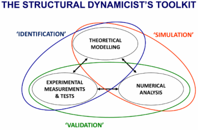
Ewins describes the skills required for designing systems in the field of structural dynamics as experimental measurements and tests (ET), Received April 10, 2026; Revised April 27, 2026; Accepted May 13, 2026; Available online June 22, 2026
Methodical Approach for the Development of Multi Domain Testing Environments 195 theoretical modelling (TM), and numerical analysis (NA), which are linked by the techniques of identification, simulation, and validation (Ewins, 2016). This provides an overall toolkit for the design of systems under dynamic, and impulsive, excitation. The toolkit is depicted in Figure 1. One relevant application where both technical systems and humans are exposed to impulse excitation are rotary hammers. As these hammers are used in various applications with different types of inhomogeneous materials, the knowledge needed for TM and NA is missing. Rotary hammers therefore need to be investigated by experimental tests (ET) during development (Ewins, 2016). One aspect that needs to be assessed with particular importance is the vibration exposure for operators, since this can lead to health issues and is additionally regulated by international standards (EU, 2002).
To investigate the interactions with real world uncertainty stemming from applications and materials, they need to be available in the controllable environment of a suitable test bench. Requirements for such substitute workpieces are reproducibility, adjustability to different workpiece properties, and capability of representing their dynamic effect in an equivalent manner. Existing substitute workpieces (Bruchmueller, Tim, 2019; PNEUROP Tools Committee, 2005; Zimprich et al., 2022) do not fulfil all of these criteria. This is also due to the challenge of measuring highly dynamic impact responses, which imposes very high requirements on sensors, and of providing extremely high damping, which in turn causes heat generation that affects the system behaviour and accelerates wear. Both challenges make it difficult for existing substitute workpieces to achieve and prove adjustability, reproducibility and equivalence in effect to real workpieces. The framework of Ewins lays a structural basis for supporting the investigation of these challenges. However, his toolkit does not address the development of testing environments. Grauberger et al. presented a design method to support the design of substitute workpieces (Grauberger et al., 2022). However, this method focuses on the simulation technique and therefore is missing aspects of the identification and validation techniques.
Figure 1: Basic skills and technologies in structural dynamics (Ewins, 2016).
Zimprich et al. proposed switching from mechanical to hydraulic substitute workpieces in order to better fulfil the desired criteria of adjustability, reproducibility and equivalence in effect (Zimprich et al., 2022). Klotz et al.
developed a concept for a hydraulic substitute base, where the tool acts as the cylinder piston and adjustability of damping characteristics is realized by changing the hydraulic resistance and capacity (Klotz et al., 2025). Research like (Matthiesen and Grauberger, 2024) provides methods for dealing with certain situations in which ET can become necessary. (Matthiesen and Grauberger, 2024) even supports the development of testing environments. However, the systematic incorporation of domain changes and mixed- domain approaches remains at a general level unanswered. Furthermore, the adaptation and specification of Ewins’ toolkit for the development of testing environments is still unclear. These limitations and the questions motivate the research question of this work: How can testing environments be developed whilst taking impulse excitation and multi-domain components into account?
The aim of this work is to provide a methodical approach for the development of testing environments with multi-domain elements for impulse excitation and adjustable damping behaviour. The proposed five step approach has been derived from the development of a hydraulic substitute base described in (Klotz et al., 2026). This substitute base is illustrated as a case study in this paper.
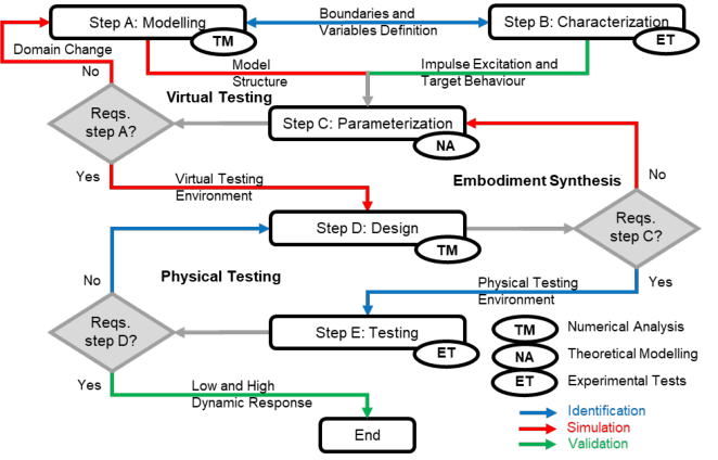
METHODICAL APPROACH FOR THE DEVELOPMENT OF TESTING ENVIRONMENTS UNDER IMPULSE EXCITATION The present work adapts and extends Ewins’ structural dynamics toolkit for development of design in structural dynamics to form a methodical development approach for testing environments under impulse excitation. The fundamental skills of TM, NA and ET are structured into a step-wise design procedure. A decision path is introduced to select appropriate techniques for each situation. Figure 2 outlines the overall scheme.
Figure 2: Scheme of the development approach for a multi domain testing environment.
Methodical Approach for the Development of Multi Domain Testing Environments 197 The approach starts with step A, ““Virtual Model Structure of the System”, as a concretization of Ewins’ TM skill, and step B, “Characterization of the Real System”, as a concretization of his ET skill; both can be carried out in parallel. In step C, “Parametrization of the Virtual Model”, representing NA, the model from step A is calibrated using the measurement data from step B. Step D, “Derivation of Design Parameters”, translates the parametrized model into design parameters, and step E, “Testing of the Testing Environment”, experimentally validates the resulting testing environment. Three iteration cycles are distinguished: a virtual testing cycle, in which the model and, if necessary, its physical domain is adapted; an embodiment synthesis cycle, in which the design is optimised; and a physical testing cycle, in which the realised testing environment is refined. Each iteration cycle may revert to the preceding cycle if further changes are required. Each step can be supported by specialised methods. The following subsections describe each step in terms of its inputs and outputs.
Virtual Model Structure of the System Aim of this step is to develop a physically motivated virtual model structure that captures the relevant physical effects of the real system under impulse excitation.
In step A, knowledge of the underlying physical effects must be derived from the literature or from step B and forms the basis for selecting appropriate modelling approaches and defining relevant states and outputs. For multi-domain systems, the interactions between domains must be defined, a suitable approach is to select a modelling method for each domain and couple them via co-simulation. Exchange variables between domains must be chosen carefully and model sub structures can be transferred systematically between domains while accounting for differing boundary conditions and physical constraints. A special focus should lie on the impulse excitation; if the excitation depends on the system behaviour, this interaction must also be modelled. Since impulses cause strong local differences due to highly dynamic interactions, system boundaries, measurement locations and simulated variables must be selected so that good agreement in step C can be achieved. A systematic sensitivity analysis of the fundamental model parameters should be carried out to assess their influence on model behaviour, and application limits should be defined based on the system behaviour derived in step B.
Input: Knowledge of relevant physical effects and suitable modelling approaches, as well as in iterative cases insights from step C.
Output: A virtual model structure representing all relevant physical effects. Together with step B, system boundaries and measurable variables are defined to enable parameter identification in step C. Requirements are that all relevant effects and impact mechanisms must be represented, and model variables must match measurable quantities in type and location.
Characterization of the Real System Aim of this step is to obtain an experimental reference for the dynamic behaviour of the system under impulse excitation.
In step B, the mechanical properties of the real system are experimentally analysed under controlled impulse excitation. The kinematics and kinetics of the system are measured at locations and for variables that are consistent with the model structure defined in step A. A target behaviour and suitable variables to describe it are derived, which may be formulated in the time or frequency domain, depending on the excitation and evaluation needs. A sensitivity analysis of the influences on the defined target variable should be carried out. If necessary, the excitation is measured independently of the system response in order to clearly separate input and output quantities.
Input: Preliminary understanding of relevant system dynamics from step A, suitable measurement methods, and an experimentally operable system with controlled excitation.
Output: An experimental data set representing the system’s dynamic behaviour under impulse excitation and the derived target behaviour.
Parametrization of the Virtual Modell Aim of this step is to parameterize and calibrate the virtual model from step A using experimental data from step B.
In step C, model-relevant parameter ranges are derived from the experimentally obtained system responses of the real system. The target behaviour from step B is compared with the simulation results of the virtual model structure from step A, and this comparison is used to adjust and refine the model parameters; where appropriate, an optimization algorithm is applied to minimise the deviation between simulated and measured responses. Design and component limits anticipated for step D, or identified during iteration, are used as constraints in the parameter identification to ensure that the resulting parameters remain physically and practically feasible. In addition, the physical feasibility of the resulting testing environment is examined, and the underlying working principle is adapted if required to ensure that the design can be realised in practice.
Input: Virtual model structure and initial parameter set from step A, experimental data from step B, and, insights on current parametrization and design options from step D, in case of an iteration.
Output: A calibrated virtual model whose parameters reproduce the target behaviour and enable the derivation of quantitative design parameters and functional requirements for the testing environment. Requirements are that the identified parameters must be physically plausible and transferable to realizable design parameters.
Derivation of Design Parameters Aim of this step is to transfer the virtual model into a realizable system architecture and to convert model parameters into design parameters.
In step D, a complete physical testing environment concept is derived based on the calibrated model from step C. The parametrized components of the model are mapped to suitable embodiments, starting with the most critical ones identified in the sensitivity analysis from step A, while pre-manufactured
Methodical Approach for the Development of Multi Domain Testing Environments 199 parts are considered wherever possible. Once the key model components have been converted into physical embodiments, a detailed system architecture is defined that incorporates the parameters from step C and other relevant functional properties. The applicability limits quantified in step A are compared with the measured behaviour of real supports and the parametrized model from step C to evaluate the transferability of the concept to real use cases, and, where necessary, design adaptations are derived from identified critical interactions and operating issues. Finally, the physical testing environment is designed as a substitute for the real system.
Input: Calibrated model from step C, applicability limits from step A, experimental insights from step B, and component data as well as design and safety constraints; in iterative cases, the current design state is also considered.
Output: Design parameters of the testing environment, including component specifications, system architecture, and design documentation, as well as the realized physical testing environment. Requirements are that the testing environment represents the parametrized model, remain within defined applicability limits, and ensure physical and practical feasibility of all components and geometries.
Testing of the Testing Environment Aim of this step is to validate the physical testing environment and to obtain a detailed understanding of its dynamic behaviour under varying operating conditions and excitation types.
In step E, experiments are performed to characterise the behaviour of the testing environment for different excitation types and system settings. The same variables defined in steps A and B are measured. To obtain a fundamental understanding, testing should start with quasi-stationary or low-frequency excitations and then progress to higher frequencies once the requirements of this step are met for the selected excitations. The target variables defined in step B to demonstrate equivalence in effect are derived and compared with those from step B. During these investigations, physical effects that were not fully captured in the modelling phase are identified, and the application limits and achievable operating range of the testing environment are explored. The experimentally determined behaviour is then compared with the simulated target behaviour to analyse discrepancies. Finally, the behaviour of the testing environment is compared with the previously characterised real system to assess the quality of representation, and a lean endurance assessment is carried out to identify life-time-critical effects and their influence on the behaviour.
Input: Manufactured testing environment from step D, calibrated model and target characteristics from step C, real system characterisation from step B, and defined test plans, excitation profiles, and system settings.
Output: An experimentally validated understanding of system behaviour across different excitations, including quantified target variables, operating limits, and identified physical effects, resulting in a validated testing environment for further development.
CASE STUDY: DEVELOPMENT OF A SUBSTITUTE WORKPIECE FOR ROTARY HAMMERS Objectives
The objective of this case study is to demonstrate the applicability of the proposed methodical approach by developing a substitute workpiece for rotary hammers. In practice, real workpieces differ strongly in their material properties and often exhibit pronounced inhomogeneity, which makes it difficult to reliably assess health-critical vibration exposure for operators during tool development. An adjustable, reproducible and effect-equivalent substitute workpiece can overcome this limitation; however, existing substitute workpieces described in the literature do not fulfil all of these criteria. The case study therefore aims to derive and validate such a substitute workpiece using the proposed five-step methodology.
Materials
A Bosch GBH 4-32 rotary hammer was selected as the reference power tool for the experiments in steps B and E, as it delivers single-impact energies of approximately 4.2 J at about 60 Hz. These single impacts exhibit dominant frequency components up to 5 kHz.
To characterise the real system in step B and to validate the testing environment in step E, experiments were conducted on a dedicated test bench, using a hand–arm model according to (Cronjäger et al., 1984) with a pneumatically applied constant feed force depicted in (Bruchmueller et al., 2019). Additionally, a high-performance shaker capable of excitations up to 3 kHz and 8 kN is used for step E. For steps A and C, a co-simulation toolkit was used to couple different physical domains: Abaqus served as the central FEM tool via its Co-Simulation Engine with FMI-based coupling, while Dymola was employed for hydraulic and multi-domain simulation, offering a dedicated solver for Abaqus and compatibility with Modelica. Measurement systems in steps B and E required high bandwidth and accuracy with minimal influence on system dynamics; therefore, strain gauges were applied directly to the chisel, based on the EPTA guideline (The European Power Tool Association, 2009). Chisel motion was measured using a Polytec PSV-400 laser vibrometer, and hydraulic pressures in the substitute workpiece were recorded with a Kistler piezoelectric pressure sensor. To ensure the required adjustability of the substitute workpiece, different real workpieces were investigated in step B, including C20/25 and C50/60 concrete as well as the Dynaload system as a state-of-the-art substitute workpiece for comparison.
CASE STUDY Virtual Model Structure of the System
As an input to this step, knowledge of previous substitute workpieces from the literature was essential. Because these approaches failed to realise a substitute workpiece that meets the criteria of adjustability, reproducibility and equivalence in effect, the substitute workpiece was transferred to the hydraulic domain. A combination of a stiff element and a damping element was chosen as a first representation of real workpieces, so the hydraulic
Methodical Approach for the Development of Multi Domain Testing Environments 201 equivalent was chosen as a hydraulic cylinder connected to an orifice. Existing experiments from the literature were used to set up the initial model, with the detailed steps described in (Klotz et al., 2025). The chisel was selected as the system boundary between rotary hammer and workpiece because it allows measurements on a component with high stiffness and low damping and thus has only a minor influence on the measured variables. The excitation at the chisel is time-dependent due to the high-frequency impacts and additionally depends on the geometry of the percussion system; therefore, the percussion system was modelled in FEM as a dynamic problem to capture the relevant excitation effects (Hasenoehrl et al., 2025). A co-simulation was set up according to (Klotz et al., 2025), in which the chisel displacement from the FEM model serves as input to the hydraulic model and the resulting hydraulic force is fed back as the force on the chisel in the FEM simulation.
The output of this step was a coupled co-simulation model representing the excitation and a model of the substitute workpiece that captures the relevant physical effects and provides force and velocity at the chisel at the chosen system boundary.
Characterization of the Real System As input, the measurement methods and the test bench described in the Materials section were used. The study plan included different real workpieces and the Dynaload system as the state-of-the-art comparison, and various chisel geometries were tested to support the objective of developing a substitute workpiece that can be adjusted to different real workpieces. To describe the system behaviour, the force and velocity of the chisel were measured, and the reflected energy from the workpiece, equal to the kinetic energy of the chisel after the contact with the workpiece, was chosen as the target variable. In addition, the exact excitation was measured on an EPTA setup to parametrise the FEM model of the rotary hammer in step C (Hasenoehrl et al., 2025).
The output of this step was a statistical description of the full kinematic and kinetic behaviour of the chisel, the reflected energy to the rotary hammer as target behaviours and the excitation by the rotary hammer.
Parameterization of the Virtual Model The input of this step was the co-simulation model of the percussion system and the hydraulic model from step A, together with the system behaviour derived in step B. First, the FEM model of the percussion system was iteratively parameterized according to (Hasenoehrl et al., 2025). For the hydraulic model, instead of using an optimisation algorithm, a wide range of system parameters was simulated and those parameter sets were selected that best matched the behaviour of the real workpieces. Since it was known that a physical orifice and hydraulic cylinder would be implemented in step D, the simulated parameters were restricted to physically feasible ranges. This approach not only allowed the hydraulic model to be calibrated to closely match the real workpieces, but also enabled the identification of the adjustment limits of the virtual model, as described in (Klotz et al., 2025),
which is important for evaluating the capability of the model to represent more than just the two workpieces quantified in step B.
The output of this step was a parameterized hydraulic model that can be directly converted into a design, since all parameters are constrained by physically realizable component designs.
Derivation of Design Parameters Step D used the hydraulic model from step C as input. First, the interface between the testing environment and the rotary hammer was defined. Next, the most relevant model components and their parameterisation were selected as in (Klotz et al., 2026) described and converted into a physical system structure: the damping element was realised using prefabricated orifices within the desired parameter range, and the stiffness element was implemented as a hydraulic cylinder with adjustment options. Additional components such as the hydraulic pump and pressure sensor connections were then selected or designed accordingly.
The output of this step is a hydraulic substitute workpiece (Klotz et al., in press).
Testing of the Testing Environment The input of this step was the measured target behaviour of the real workpieces from step B, the parameter sets from step C and the hydraulic substitute workpiece from step D. First, the quasi-stationary system behaviour was tested to gain insight into the stationary properties such as leakage and to establish a baseline for changes over the lifetime of the substitute workpiece. The excitation frequency was then increased to verify that the dynamic properties correspond to the model, before switching to the rotary hammer excitation frequency to investigate the full adjustment range and the equivalence in effect to the real workpieces.
The output of this step will be a validated substitute workpiece.
DISCUSSION
The proposed methodical development approach builds on Ewins’ structural dynamics toolkit and makes it operational for the specific task of developing testing environments under impulse excitation. While Ewins conceptually integrates theoretical modelling, numerical analysis and experimental testing via simulation, identification and validation, his work remains at a strategic level and does not specify a concrete, step-wise process for the development of test environments or substitute workpieces. In contrast, the present work refines these skills into the five steps A–E, each with defined inputs, outputs and requirements, and explicitly introduces iteration cycles. Compared to the approach by Grauberger et al., the approach presented here has a broader scope. Grauberger et al. focus on a simulation-centric design of a substitute workpiece with a defined coefficient of restitution and on the economic optimisation of the frame structure. The methodical approach in this work extends these
Methodical Approach for the Development of Multi Domain Testing Environments 203 ideas by adding explicit steps for experimental characterisation of the real system and testing of the physical testing environment, including a possible multi-domain approach and domain change. This provides more guidance across the entire development process, from initial virtual modelling to a validated testing environment. The case study shows that the methodical approach supports several fundamental challenges in the development of testing environments for impulse-excited systems. First, the explicit treatment of multi-domain aspects allows the transfer of simple stiffness and damping concepts into a hydraulic realisation with adjustable parameters. Second, the introduction of steps with clearly defined iteration triggers helps to systematically manage modelling assumptions, identify missing physical effects and refine both the virtual model and the physical test setup. Third, the consistent use of target behaviour and equivalence in effect as central validation concepts ensures that the substitute workpiece reproduces the relevant dynamic behaviour of real systems within defined limits. However, the current work also has limitations. The methodical approach has been demonstrated on a single use case with a rotary hammer and a hydraulic substitute workpiece, so its generalisability to other impact systems remains to be shown. Moreover, the case study has so far been implemented only up to step D, while the final validation in step E is still ongoing. In addition, only the transfer to a hydraulic system was considered; other domains have not yet been investigated. Future research should therefore examine further case studies with different impulse excitations, explore alternative domain combinations and derive more general guidelines for modelling, identification and validation techniques within the proposed five-step process.
CONCLUSION
This paper presents a five-step, multi-domain-capable methodical approach that further develops Ewins’ structural dynamics toolkit into a methodical approach for the development of testing environments under impulse excitation and demonstrates its applicability through the systematic design and validation of an adjustable, reproducible and effect-equivalent substitute workpiece for rotary hammers. The methodical approach structures virtual modelling, experimental characterisation, parameterisation, derivation of design parameters and testing into clearly defined steps with explicit inputs, outputs and requirements, and supports domain changes, for example from mechanical to hydraulic systems, via co-simulation. By doing so, it addresses current challenges in developing testing environments that realistically reproduce highly transient impact phenomena while remaining controllable and repeatable, and it closes a gap between existing strategic toolkits and case-specific test rig designs in the literature.
ACKNOWLEDGMENT
The project upon which this publication is based was funded by the Deutsche Forschungsgesellschaft (DFG, German Research Foundation) under the project ID 517363628. The authors gratefully acknowledge the support. The language in this publication was enhanced with the help of artificial intelligence.
All authors have read and agreed to the published version of the manuscript.
REFERENCES
Bruchmueller, T., Huegel, N., Wacker, S. and Matthiesen, S. (2019) ‘Modelling of Tool Workpiece Interactions—Coefficient of Restitution for Hammer Drilling of Concrete’, Forschung im Ingenieurwesen, vol. 83, no. 1, pp. 21–30. Bruchmueller, Tim (2019) Realistic and reproducible boundary conditions in
vibration analysis - A substitute substrate for electropneumatic drilling hammers, Dissertation, Karlsruhe, Karlsruher Institut für Technologie. Cronjäger, L., Jahn, R. and Riederer, H. (1984) Development of a test rig for the reproducible measurement of the vibration of impacting hand-held machines, Wiesbaden, VS Verlag für Sozialwissenschaften. EU (2002) ‘DIRECTIVE 2002/44/EC OF THE EUROPEAN PARLIAMENT
AND OF THE COUNCIL of 25 June 2002 on the minimum health and safety requirements regarding the exposure of workers to the risks arising from physical agents (vibration)’, Official Journal of the European Communities. Ewins, D. J. (2016) ‘Exciting vibrations: the role of testing in an era of supercomputers and uncertainties’, Meccanica, vol. 51, no. 12, pp. 3241–3258. Grauberger, P., Bruchmüller, T., Zimprich, S. and Matthiesen, S. (2022) ‘Considering
Manufacturing in Functional Modelling - Case Study on Combination of Simulation-Driven Design with Design-for-Manufacture’, Procedia CIRP, vol. 109, pp. 701–706. Hasenoehrl, S., Klotz, J., Geimer, M. and Matthiesen, S. (2025) ‘Simulation of Strain Waves in Impact Driven Tools: Towards Virtual Testing of an Adjustable Substitute Workpiece’, NAFEMS World Congress. Klotz, J., Hasenoehrl, S., Dr.-Ing. Matthiesen, S. and Prof. Dr.-Ing. Geimer Marcus
(2025) ‘Co-simulation of a hydraulic substitute base for the effect-equivalent modeling of mineral materials: Co-simulation of a Hydraulic Substitute Base for the Effect-equivalent Modelling of Mineral Materials’, Proceedings of the 36th Symposium Design for X. Klotz, J., Hasenoehrl, S., Matthiesen, S. and Geimer, M. (2026) ‘Hydraulic Substitute Base for Demolition Hammers’, International Fluid Power Conference, vol. 15. Klotz, J., Hasenoehrl, S., Matthiesen, S. and Geimer, M. (in press) ‘Design of a
Hydraulic Substitute Base for Demolition Hammers’, Human Interaction and Emerging Technologies (IHIET2026). Matthiesen, S. and Grauberger, P. (2024) Design knowledge for engineers, Berlin, Heidelberg, Springer Berlin Heidelberg.
Methodical Approach for the Development of Multi Domain Testing Environments 205 PNEUROP Tools Committee (2005): DYNALOAD - design, construction, use and
maintenance.: PNEUROP Publication. The European Power Tool Association (2009): EPTA Procedure 05/2009. Zimprich, S., Anstotz, B. and Matthiesen, S. (2022) ‘Hydro-mechanical Dampers for Testing high Cyclic Shock Loads in Preventive Health Protection’, Human Interaction and Emerging Technologies (IHIET2022), vol. 68, pp. 683–689.
LISTED IN THE AHFE DIGITAL BOOKSTORE CATALOGUE
Explore the complete digital volume
Human Interaction and Emerging Technologies (IHIET-FS 2026): Future Systems and Design Applications
Read this individual research paper free through the original publisher, or explore the full digital proceedings book.
ISBN 979-8-950676-11-6
Explore this ISBN in the AHFE Bookstore ↗Listed in the July 2026 bookstore catalogue; search by ISBN to confirm current availability · Digital book purchase optional