Rafał Przesmycki, Marek Bugaj, Jarosław Bugaj, Paweł Skokowski, Krzysztof Malon, Michał Kryk (2026). A method of increasing the electromagnetic immunity of the Spectrum Monitoring Sensor to UAV’s by using a shielded casing. In: Human Factors in Simulation, Software and Systems Engineering. AHFE Open Access, vol. 220, pp. 38–48. https://doi.org/10.54941/ahfe1007692
The article presents a method for increasing the electromagnetic immunity of a spectrum monitoring sensor installed on an unmanned aerial vehicle (UAV) through the use of a specially designed shielded enclosure. The paper describes the design and implementation process of the shielded casing, focusing on limiting the influence of external electromagnetic disturbances on the sensor’s sensitive electronic components. The design solutions included the selection of materials with high shielding effectiveness over a wide frequency range, the application of filters and feedthroughs to suppress conducted interference, and the use of conductive gaskets to ensure electromagnetic continuity of the enclosure. The effectiveness of the proposed solutions was verified through laboratory tests of radiated and conducted emissions conducted in accordance with the MIL-STD-461G standard, including RE102 and CE102 measurements. Comparative tests performed for the sensor operating with and without the shielded enclosure demonstrated a significant reduction in emission levels in critical frequency ranges. The results confirm an improvement in electromagnetic compatibility and increased immunity of the sensor to interference generated by UAV onboard systems. The study shows that a properly designed shielded enclosure is an effective and practical approach to enhancing electromagnetic immunity of sensors used on UAV platforms and provides valuable guidelines for protecting other electronic devices operating in high-interference environments.
Unmanned aerial vehicles (UAV’s) have become a cornerstone of modern civilian and military infrastructure, serving roles in environmental monitoring, surveillance, and electronic reconnaissance. Rapid advancements in electronics and component miniaturization facilitate the integration of increasingly advanced payloads into small-scale platforms. Of particular significance are spectrum monitoring sensors, which are designed to detect, identify, and analyze electromagnetic signals across a broad frequency spectrum.
A Method of Increasing the Electromagnetic Immunity of the Spectrum Monitoring Sensor 39 However, installing such sensors on UAV platforms poses significant electromagnetic compatibility (EMC) challenges. Unmanned systems are characterized by a high density of electronic devices operating simultaneously in close proximity. Onboard communication systems, GNSS receivers, power converters, motor controllers, flight control systems, and telemetry modules generate both radiated and conducted broadband electromagnetic interference. This interference can degrade the performance of sensitive measurement systems, leading to decreased detection sensitivity, increased noise, measurement instability, and reduced data quality.
Ensuring adequate electromagnetic immunity for sensors is therefore a key aspect of UAV system design. Unlike ground-based devices, onboard equipment is subject to stringent Size, Weight, and Power (SWP) constraints. These limitations significantly hinder the application of traditional interference reduction methods, necessitating compact, lightweight, and effective solutions. One of the most practical approaches is the use of custom- engineered shielded enclosures, intended to protect sensitive electronic systems from undesirable electromagnetic fields.
Shielding effectiveness (SE) depends on several factors, including material properties, enclosure geometry, the quality of electrical bonds, and the design of interfaces such as connectors, cable entries, and ventilation apertures. An improperly designed enclosure can result in gaps and discontinuities, significantly compromising shielding performance, especially at higher frequencies. Furthermore, conducted interference transmitted via power and signal lines represents a major coupling mechanism in UAV systems, necessitating the integration of high-performance filters and EMC feedthroughs into the enclosure design.
Verifying the effectiveness of electromagnetic protection measures requires laboratory testing in accordance with applicable standards. The MIL-STD-461G standard is the primary reference for military and aviation systems, defining measurement methodologies and limit levels for radiated and conducted emissions. Procedures such as RE102 (Radiated Emissions) and CE102 (Conducted Emissions) provide an objective basis for assessing the electromagnetic compatibility (EMC) of electronic devices in rigorous operating environments.
This article presents a comprehensive approach to enhancing the electromagnetic immunity of a spectrum monitoring sensor (SMS) intended for UAV platforms through the development of a dedicated shielded enclosure. The work details the design process, material selection, and the integration of filtering elements into the enclosure. The effectiveness of the proposed solutions was verified through comparative laboratory tests of the SMS sensor operating both with and without the shielded enclosure. The results confirm a significant improvement in electromagnetic compatibility and heightened immunity to interference generated by onboard UAV systems.
CHARACTERISTICS OF THE SPECTRUM MONITORING SENSOR AND SHIELDED ENCLOSURE The Spectrum Monitoring Sensor (SMS) is a specialized measurement instrument designed to detect, record, and analyze electromagnetic signals
across a wide frequency range. Its primary function is to identify radio signals and characterize their frequency parameters and power levels – capabilities essential for electromagnetic spectrum surveillance and electronic reconnaissance. In this solution, the sensor was adapted for onboard operation on an unmanned aerial vehicle (UAV), necessitating compliance with stringent environmental and operational requirements.
The purpose of a spectrum monitoring sensor as a component of a reconnaissance and electronic warfare system, used both in peacetime and during military operations, is to facilitate the functionality of any strategy that allows for the acquisition of information from the surrounding electromagnetic environment. In practice, two aspects of this very broad topic are primarily addressed: signal detection and classification. While detection is merely a binary decision about the presence or absence of a radio signal in the air, signal classification encompasses much more advanced analysis techniques that allow for the identification and/or estimation of signal parameters, such as the type of modulation used or the signal bandwidth. Classification is not considered a feature of the SMS within the proposed system. The primary challenge in spectrum monitoring lies in developing high-quality hardware and algorithms for signal detection and data dissemination. Energy detectors can ensure precise detection provided they are sufficiently close to the emitter, have adequate integration time, or receive a signal with sufficient strength. The developed SMS enhances these capabilities by leveraging the UAV’s mobility to monitor large areas while mitigating propagation obstacles. By maintaining an optimal altitude and achieving Line-of-Sight (LOS) conditions, the sensor can operate in closer proximity to the source. Furthermore, the SMS features an external interface designed for the efficient transmission and management of recorded signal data.
To mitigate the impact of undesirable electromagnetic interference, a dedicated shielded enclosure was developed as an integral component of the SMS. The enclosure’s primary purpose is to provide high shielding effectiveness across a wide frequency range, while maintaining the low weight and compact dimensions required for aviation applications. The enclosure’s design was designed with the constraints of the SWP and mounting conditions on the UAV platform in mind.
The enclosure is made of a conductive material with high electromagnetic field suppression efficiency, ensuring electrical continuity of the entire structure. Cable entries and signal and power connectors are a key element of the shielded enclosure design. To reduce conducted interference, appropriate EMC filters and entries integrated into the enclosure walls are used, ensuring the suppression of unwanted signals while maintaining the proper functionality of the electronic circuits. Additionally, conductive gaskets are used at the junctions between the enclosure covers and panels, ensuring continuous electromagnetic shielding and increasing the structure’s resistance to vibration and changing environmental conditions. Two honeycomb panels are used to ensure airflow and heat dissipation from the enclosure interior.
Based on the specified requirements regarding the maximum dimensions and weight required for integration with the UAV platform, the enclosure was
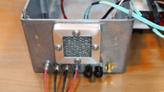
A Method of Increasing the Electromagnetic Immunity of the Spectrum Monitoring Sensor 41 selected and used for the SMW project. It is a Hammond Electronics 1590EE enclosure, made of die-cast aluminum. The enclosure’s external dimensions are 200 × 120 × 84 mm. The enclosure is secured with six screws, although the standard design can be retained or the proposed method of additionally securing the inspection plate can be used to improve shielding effectiveness. The general appearance of the shielded enclosure is shown in Fig. 1.
Figure 1: Appearance of a shielded enclosure based on the Hammond electronics 1590EE enclosure with connectors and a ventilation panel.
The sensor’s components (USRP B200 mini programmable SDR radio module, Raspberry Pi 4B microcomputer, Ethernet/RJ45 fiber optic converter) are arranged and mounted inside a shielded enclosure in a manner optimized for available mounting space, cable management, and maintaining the electromagnetic properties of the entire structure. The arrangement of components, along with cable connections, is designed to allow for easy enclosure closure, ensure mechanical stability during operation, and limit radiated emissions.
CONDUCTED EMISSION MEASUREMENTS Depending on the intended use of the unmanned aircraft systems (UAS), the UAS manufacturer must meet the relevant requirements for products used in the civilian or military sphere. This also applies to systems mounted on board UAS. Delegated Regulation 2019/945 establishes rules for the placing on the European Union internal market and the free movement within the EU of UAS intended for operation within the open category. These rules include the manufacturer’s obligation to assess the product’s conformity (i.e., UAS assessment) with the requirements specified in detail in the annex to the Delegated Regulation and the relevant harmonized standards. Therefore, UAV’s operated in the open category must meet the requirements of the Electromagnetic Compatibility Directive, which requires drones to emit minimal electromagnetic interference and be resistant to such interference. UAV’s operated in a military environment must meet the requirements of dedicated defense standards applicable in a given country.
For this reason, based on the defence standard regarding electromagnetic compatibility MIL-STD461G and the CE102 procedure, a measuring station was set up for testing conducted emissions of sensors mounted on board an unmanned aerial vehicle.
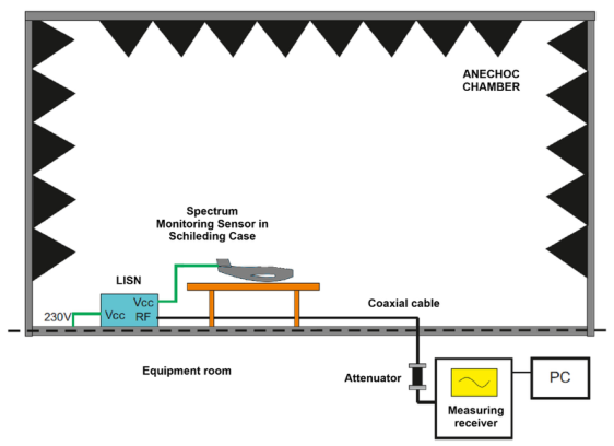
A block diagram of the station for measuring conducted disturbances emitted by unmanned aerial vehicles is shown in Fig. 2. Measurements of conducted disturbances emitted by sensors mounted on board an unmanned aerial vehicle involve measuring the voltage value in the sensor’s power supply lines using an artificial network and a measuring receiver in the frequency range from 10 kHz to 10 MHz. Measurements are performed for the L1(+) line and reference ground, and the N(–) line and reference ground.
Figure 2: Block diagram of the laboratory stand for measuring conducted interference emitted by the SMS sensor.
RADIATED EMISSION MEASUREMENTS RE102 tests, according to the MIL-STD-461G standard, evaluate radiated emissions from a sensor designed for unmanned aerial vehicles (UAV’s). These tests verify electromagnetic compatibility (EMC) for military environments, specifically regarding integration with aircraft platforms.
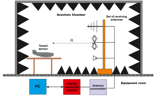
A block diagram of the measurement station for testing radiated disturbances emitted by a spectrum monitoring sensor mounted on board an unmanned aerial vehicle is shown in Fig. 3. The station includes the sensor under test, a set of measurement antennas, a measurement receiver, and auxiliary components necessary for the proper implementation of the test procedure. RE102 radiated emission measurements involve measuring the electromagnetic field intensity emitted by the sensor under test at a distance of 1 m from its housing, using measurement antennas and a measurement receiver. The measurement frequency range covers the 10 kHz to 18 GHz band, in accordance with the MIL-STD-461G standard, allowing for the assessment of emissions generated by digital circuits, power converters, and
A Method of Increasing the Electromagnetic Immunity of the Spectrum Monitoring Sensor 43 the sensor’s radio paths. Measurements are performed for two orthogonal measurement antenna polarizations – vertical and horizontal – to identify the maximum radiated emission level.
Figure 3: Block diagram of a laboratory stand for measuring radiated interference emitted by the SMS sensor.
MEASUREMENT RESULTS This chapter presents the results of conducted and radiated emission measurements for a spectrum monitoring sensor. The tests were performed to assess the level of electromagnetic interference generated by the sensor during operation under nominal conditions and to verify compliance with the electromagnetic compatibility requirements specified in the MIL-STD- 461G standard. These results provide a basis for analyzing the impact of the SMS sensor operation on the electromagnetic environment and for assessing the feasibility of its safe integration with other systems on an unmanned aircraft platform.
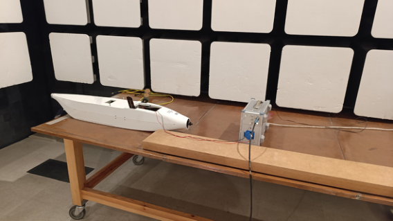
Figure 4: View of the SMS sensor during measurements of conducted disturbance emissions in the frequency range from 10 kHz to 10 MHz.
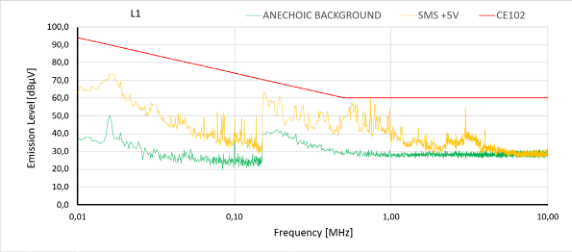
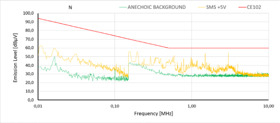
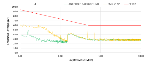
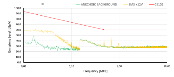
In accordance with the CE102 procedure, conducted emission measurements were performed across the 10 kHz to 10 MHz frequency range. Two power supply configurations were tested: the +5 V line powering the main sensor modules and the +12 V line for the LAN optical converter. The experimental setup of the SMS is illustrated in Fig. 4, while Figures 5 through 8 present the recorded conducted emission levels.
Figure 5: The voltage value of conducted disturbances at the power supply terminals generated by the SMS in the frequency range from 10 kHz to 10 MHz on Line L1(+) for +5 V power supply (power supply of the main sensor modules) and noise background.Figure 6: The voltage value of conducted disturbances at the power supply terminals generated by the SMS in the frequency range from 10 kHz to 10 MHz on Line N(–) for +5 V power supply (power supply of the main sensor modules) and noise background.Figure 7: The voltage value of conducted disturbances at the power supply terminals generated by the SMS in the frequency range from 10 kHz to 10 MHz on Line L1(+) for +12 V power supply (power supply of the optical fiber to LAN converter) and the noise background.Figure 8: The voltage value of conducted disturbances at the power supply terminals generated by the SMS in the frequency range from 10 kHz to 10 MHz on the N(–) Line for +12 V power supply (power supply of the optical fiber to LAN converter) and the noise background.
Emission generated by the SMS powered by +5 V (yellow line) shows an elevated level in the frequency range of 0.1–5 MHz. In this region, the emission level is significantly higher than background, indicating the dominant influence of the sensor’s power supply and switching converters. Despite this, the maximum emission values remain below the CE102 limit curve, maintaining the required safety margin. Based on the obtained results, it can be concluded that the SMS meets the conducted emission requirements for both power lines, and the level of generated interference does not exceed the limits specified by the CE102 curve across the entire analyzed frequency band. The same is true for the used fiber optic/LAN converter powered by +12 V.
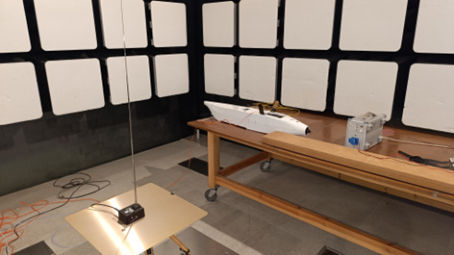
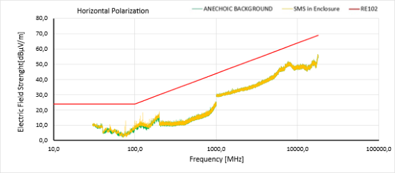
Based on the described method, radiated disturbance measurements were performed in the frequency range of 10 kHz to 18 GHz for two cases: a spectrum monitoring sensor without a enclosure and one placed in a shielded enclosure. Subsequently, the sensor was tested while mounted on a UAV platform within the shielded enclosure. Fig. 9 illustrates the SMS during electric field strength measurements, while Figures 10 to 13 present the results across the full 10 kHz to 18 GHz range.
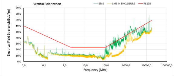
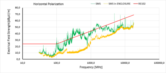
Figure 9: View of the SMS during measurement of the electric field strength placed in the enclosure in the frequency range from 10 kHz to 30 MHz with the V polarization of the measuring antenna.Figure 10: Comparison of the electric field intensity of the radiated emission generated by the SMS and the SMS placed in the enclosure in the frequency range from 10 kHz to 18 GHz with V polarization.Figure 11: Comparison of the electric field intensity of the radiated emission generated by the SMS and the SMS placed in the enclosure in the frequency range from 30 MHz to 18 GHz with H polarization.
The figures illustrate the radiated emission results for the SMS across both vertical and horizontal antenna polarizations. In the low-frequency range up to approximately 100 MHz, emission levels for both the unhoused sensor and the one in a shielded enclosure are comparable and remain significantly below the limit curve. In this region, emissions are dominated by power supply systems and slowly varying digital signals, where the impact of the shielded enclosure is limited.
In the frequency band from 100 MHz to 18 GHz, a significant increase in radiated emission levels is observed, characterized by numerous narrowband components exceeding the RE102 limit. The application of a shielded enclosure markedly reduces emissions in this range, resulting in a downward shift of the emission profile by approximately 10 to 15 dB compared to the unenclosed configuration. Across the entire analyzed spectrum, the emissions of the shielded sensor remain below the MIL-STD-461G limit curve, maintaining the required safety margin.
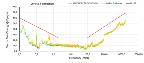
The results regarding the radiated emissions from the SMW sensor integrated into the UAV structure clearly confirm the effectiveness of the shielded enclosure in suppressing emissions, particularly in the high-frequency range. The use of this enclosure ensures compliance with RE102 requirements
A Method of Increasing the Electromagnetic Immunity of the Spectrum Monitoring Sensor 47 and significantly improves the sensor’s electromagnetic compatibility (EMC) when operating as part of a UAV platform.
Figure 12: The value of the radiated emission generated by the SMS placed in the enclosure on board the UAV in the frequency range from 10 kHz to 18 GHz (V polarization).Figure 13: The value of the radiated emission generated by the SMS placed in the enclosure on board the UAV in the frequency range from 10 kHz to 18 GHz (H polarization).
CONCLUSION
This article presents the design of a shielded enclosure for a spectrum monitoring sensor (SMS) intended for UAV integration. The design was developed considering the UAV platform’s weight and size constraints as well as the electromagnetic compatibility (EMC) requirements of military standards. Utilizing an aluminium enclosure and a specialized electronics mounting system resulted in a structure with high mechanical stability and consistent shielding continuity. Key factors included the strategic arrangement of internal components, ensuring robust galvanic connections between metal elements, and minimizing gaps or apertures that could compromise shielding effectiveness.
Conducted emission tests demonstrated that the interference levels generated by the SMS remain below the regulatory limits throughout the analyzed frequency range. Notably, a significant safety margin was
achieved even in the low-frequency range, where emissions from power supplies and switching converters typically predominate. Radiated emission measurements, performed in accordance with the MIL-STD-461G RE102 procedure, confirmed the effectiveness of the shielded enclosure. Compared to the unhoused configuration, the shielding significantly attenuated radiated emissions, ensuring they remained below the RE102 limit curves across the entire tested spectrum while maintaining the required safety margin.
In summary, the shielded enclosure designed for the spectrum monitoring sensor meets all structural and electromagnetic specifications, enabling the safe integration of the sensor with the UAV platform. The proposed solution provides a solid foundation for the further development of sensors intended for environments with stringent EMC requirements, as well as for adapting enclosure variants for other system components.
ACKNOWLEDGMENT
This work was financed by Military University of Technology under research project entitled “Testing of radiated emission disturbances of selected smartphones using an anechoic chamber and an OTEM chamber in the aspect of the requirements of the PN-EN 17025 standard”.
The authors carried out the research using equipment purchased as part of the project “Polish Network of EMC Laboratories (EMC-LabNet)”, (POIR.04.02.00-02-A007/16).
REFERENCES
Commission Implementing Regulation (EU) 2019/947 on the rules and procedures for the operation of unmanned aircraft, Official Journal of the European Union, L 152. 2019. D. R. Somolinos et al., “Shielding Effectiveness Measurement of an UAV Simplified
Demonstrator Through Low-Level Swept Field (LLSF) Test,” in IEEE Transactions on Electromagnetic Compatibility, vol. 64, no. 5, pp. 1665–1673, Oct. 2022, doi: 10.1109/TEMC.2022.3202636. J. Yang, H. Zhou, Y. He, L. Xu and X. Shi, “Research on Shielding Effectiveness of UAV Based on Neural Network,” 2024 IEEE International Workshop on Radio Frequency and Antenna Technologies, Shenzhen, China, 2024, pp. 345–348. Mil-Std-461G, Requirements for the control of electromagnetic interference
characteristics of subsystems and equipment, U.S. Department of Defense, Washington D.C. 2015. R. Kubacki, R. Przesmycki, D. Laskowski. 2023. “Shielding Effectiveness of Unmanned Aerial Vehicle Electronics with Graphene-Based Absorber” Electronics 12, no. 18: 3973. R. Przesmycki, R. Kubacki, “EMC requirements for equipment used in the polish
army - Impact of changes the NO-06-A500:2012 standard on the measuring results”. 20th International Conference Microwaves, Radar, and Wireless Communication, 2014.
LISTED IN THE AHFE DIGITAL BOOKSTORE CATALOGUE
Explore the complete digital volume
Human Factors in Simulation, Software and Systems Engineering
Read this individual research paper free through the original publisher, or explore the full digital proceedings book.
ISBN 978-1-964867-96-0
Explore this ISBN in the AHFE Bookstore ↗Listed in the July 2026 bookstore catalogue; search by ISBN to confirm current availability · Digital book purchase optional