Rafał Przesmycki, Marek Bugaj (2022). The measurement of baseband frequency range for military satellite terminals. In: Human Interaction & Emerging Technologies (IHIET 2022): Artificial Intelligence & Future Applications. AHFE Open Access, vol. 68, pp. 252–260. https://doi.org/10.54941/ahfe1002740
VSAT stations (Very Small Aperture Terminals) are small, cheap terrestrial satellite stations, which are equipped with small antennas (typically from 1 m to 2 m), low power RF transmitters (typically from 0.5 W to 2 W) and in modems and signal converters, forming a compact structure. Stations can be very easily installed on the roof, wall or car park in front of the user's office, where the end devices are placed. Stations can be used in a very convenient and economical way to connect end users devices to the main computer located in a remote data center. VSAT stations are usually used to transmit digital data.VSAT stations often work in a star network. VSAT stations communicate with a large ground station, called the central station. In this case, the type of modulation, transmission rate, coding and access methods for the outgoing channel (from the central station to the VSAT station) and for the incoming channel (from the VSAT station to the central station) are usually differentiated, in order to use the satellite channel effectively, using methods multiplied access. In this type of VSAT networks, user data is usually processed by VSAT stations and the central station, so as to effectively support various computer network protocols.The article concerns problems related to electromagnetic compatibility of military satellite terminal with small VSAT antennas (Very Small Aperture Terminals). The article focuses on the measurement of the frequency range of military satellite terminal work in the basic band for VSAT satellite terminals intended for data transmission. The article presents a laboratory stand and a method for measuring the operating frequency in the basic band for VSAT satellite terminals, which was developed on the basis of European civil standards and a military standard containing requirements on the operating frequency in the basic band for VSAT. In the case of measuring the operating frequency in the basic band for satellite terminals of the tested device, we must remember to estimate the uncertainty of the measurement. The extended value of the uncertainty of measurement for individual frequency ranges is determined from the f0± 2*10^-7 relationship.
VSAT stations (Very Small Aperture Terminals) are small, cheap terrestrial satellite stations, which are equipped with small antennas (typically from 1 m to 2 m), low power RF transmitters (typically from 0.5 W to 2 W) and in modems and signal converters, forming a compact structure. Stations can be very easily installed on the roof, wall or car park in front of the user’s office, where the end devices are placed. Stations can be used in a very convenient and economical way to connect end users devices to the main computer loca- ted in a remote data center. VSAT stations are usually used to transmit digital data.
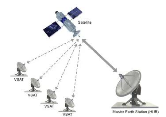
VSAT stations often work in a star network, as shown in Figure 1. VSAT stations communicate with a large ground station, called the central station. In this case, the type of modulation, transmission rate, coding and access methods for the outgoing channel (from the central station to the VSAT sta- tion) and for the incoming channel (from the VSAT station to the central station) are usually differentiated, in order to use the satellite channel effe- ctively, using methods multiplied access. In this type of VSAT networks, user data is usually processed by VSAT stations and the central station, so as to
The Measurement of Baseband Frequency Range for Military Satellite Terminals 253
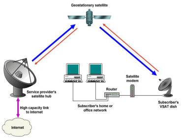
Figure 1: VSAT network - star configuration.Figure 2: VSAT network with point-to-point configuration.
effectively support various computer network protocols. Point-to-point con- nections between VSAT stations are also used, as shown in Figure 1. In this case, the type of modulation and the format of the signals transmitted and received by the VSAT station is usually the same, and the user data usually passes through the VSAT network in a transparent manner without protocol processing. To the manage and supervise the configuration and operation of the network is usually used computer.
Point-to-point connections between VSAT stations are also used, as shown in Figure 2. In this case, the type of modulation and the format of signals tran- smitted and received by the VSAT station is usually the same, and user data usually pass through the VSAT network in a transparent manner, without protocol processing. To manage and supervise the configuration and ope- ration of the network, a management and supervisory computer is usually used.
GENERAL COMMENTS ON METHODS OF MEASUREMENT VSAT TERMINALS The RF port of an ODU device is usually connected directly to a tube radiator. In this case, the antenna with the radiator must be separated from the rest of the ODU, using the instructions developed by the manufacturer, in order to enable measurements of the antenna parameters and RF parameters at the contact point. Sometimes, it may be necessary to use appropriate adapters or
254 Przesmycki and Bugaj
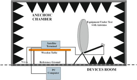
Figure 3: General block diagram of the measurement stand in the anodising chamber used in the study of satellite terminals.
waveguides to connect the measuring instruments with the contact point. The general block diagram of the measuring station in the annealing chamber used during the examination of the VSAT satellite terminals is shown in Figure 3.
There is a control function in the VSAT station that prohibits the RF signal output when the VSAT station operating in the star topology does not receive the appropriate permission signal from the central station. It may be necessary to use the manufacturer’s instructions to force the broadcast of the VSAT station - by omitting the control function or by using a central station simulator, equipped with a supervisory computer and its emulator, which generates a control signal During measurements, conditions that could damage the tested devices should be avoided. If this is not specifically indi- cated, the measurements should be carried out under normal conditions for power supply, temperature, air pressure, humidity and output load. Once the device has been prepared for operation under specified conditions, these conditions should be left unchanged during all measurements, unless these conditions are to be specially changed for a specified period of time or for a specific measurement.
MEASURE OF THE OPERATING FREQUENCY RANGE IN BASE BAND FOR VSAT TERMINALS The method of measuring the operating frequency range in the basic band for VSAT satellite terminals has been developed on the basis of the follow- ing standards: “PN-EN 60835-3-13: 2000 - Methods of measurement for equipment used in digital microwave radio transmission systems - part 3: Measurements on satellite earth stations - section 13: VSAT systems” and “PN-EN 60835-1-2: 2002 Methods of measurement for equipment used in digital microwave radio transmission systems - Part 1: Measurements com- mon to terrestrial radio-relay systems and satellite earth stations - Section 2: Basic characteristics”. However, the requirements for the operating frequency band in the basic band for VSAT satellite terminals are contained in STANAG 4484 Edition 2. The requirements are as follows: a intermediate frequency of 140 MHz is recommended and for L band in the range of 450 MHz to
The Measurement of Baseband Frequency Range for Military Satellite Terminals 255
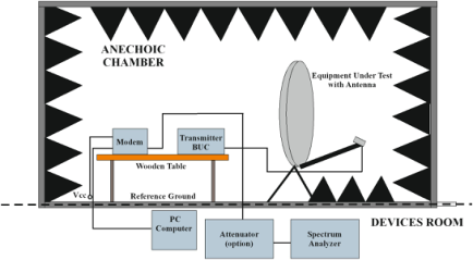
Figure 4: Block diagram of a laboratory stand in an anechoic chamber used in testing satellite terminals when measuring the maximum harmonic level.
2000 MHz with a jump of 25 kHz. In general, within the developed measu- rement method, it should be possible to transmit a continuous carrier wave through the VSAT terminal, using local setting or remote control. A pseudo- random bit sequence should be fed to the VSAT terminal modulator input and then the spectrum analyzer should be connected to the RF port. Then measure the spectrum of the output signal. The detailed requirements for the operating frequency band in the basic band for VSAT satellite terminals are discussed in the following subsections.
Measuring Systems According to the PN-EN 60835-3-13: 2000 standard, for the operating fre- quency in the basic band for VSAT satellite terminals, it is necessary to set up the laboratory stand in the configuration as shown in Figure 4.
Authentication of the Measuring Path The measurement path should be subject to authentication on the section from the RF output of the tested device to spectrum analyzer. In order to authenticate the track:
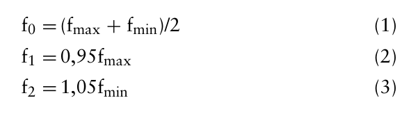
a) turn on the power of the measuring instruments and leave them in this state for the time necessary to obtain the proper stability, b) provide from the signal generator a reference signal of a known level and at a fundamental frequency f0 equal to the center frequency of a given sub-range of the transmitter. The center frequency should be determi- ned according to the relationship (paragraphs 2.3.10.2 of NO-06-A500: 2012):
Equation reproduced from the original PDF.
in which: f0 - the frequency of tuning the device or block, fmax - the upper frequency of the device (block) sub-range,
256 Przesmycki and Bugaj
fmin - the lower frequency of the device (block) sub-range. c) tune the spectrum analyzer to the frequency f0 and check if the frequency of the measured signal is within the range of the allowable measurement error of ± 0,1% with f0, d) if the measurement error does not fall within the range of the admissible measurement error ± 0,1 % with f0, locate the error source and remove the cause of the error before proceeding with the EUT tests. e) repeat the operations described in item b) to d) for the two extreme frequencies of the sub-range under consideration.
The Main Measurement Procedure During the measurements, it should be possible to transmit a continuous car- rier wave (preferably unmodulated) using a local settings or remote control. Attach the frequency counter to the RF port of the ODU (outdoor device), measure and record the carrier frequency (for the limiting frequencies shown in Table 1). Change the frequency using local settings and/or remote and check if the carrier frequency changes according to the control. If required, accuracy and stability should be measured at several carrier frequencies.
The bandpass filter should only be used in the presence of interfering signals. The use of an amplifier or a silencer is necessary when the levels of the measured signal do not correspond to the levels of signals required by the frequency meter. It is recommended that the tested device and measuring instruments reach the state of thermal stability before starting measurements. The reading from the digital frequency meter follows the end of the coun- ting period, for example, after one second. You can also register the digital frequency meter’s indications from several counting periods. The number of counting periods used for measuring depends on the presence of disturbances and on the fact whether interference modulates the measured signal or over- laps it. Statistical analysis of a series of averaged results from several counting periods allows to validate the measurement results.
The above method is also applicable in the case of modulating the RF signal by a baseband signal with a zero mean value, provided that the digital frequ- ency meter does not introduce errors depending on the modulation signal. It is recommended that the period of averaging the digital frequency meter be not less than 100 periods of the modulating signal. However, in cases where we perform frequency measurements in the presence of modulating signals, for which the averaging time should be eg 10 s or more, it is permissible to perform several measurements with a short averaging period, and then to recalculate the average value from the obtained results.
Measurement Procedure In order to measure the operating frequency band in the basic band for VSAT satellite terminals, perform the following steps:
a) Turn on the power of the measuring instruments and leave them in this state for the time necessary to obtain the proper stability. b) Set up the tested terminal on a laboratory stand in accordance with Figure 4, run the tested object in accordance with its instruction manual.
The Measurement of Baseband Frequency Range for Military Satellite Terminals 257
c) Switch off the positioning of the antenna system in the terminal. d) Configure the tested terminal to work with the minimum available signal strength. e) Set the transmitter frequency to the minimum frequency of the baseband in the tested terminal. f) Using the spectrum analyzer, measure the center frequency of the signal from the transmitter. g) Record (save) the result of the measurement.
Points e), f) and g) shall be performed for the maximum frequency of the transmitter in the baseband, respectively.
Display of Test Results According to the EN 60835-1-2 standard: Methods of measurement for digi- tal infrared radio transmission systems - Part 1: Measurements common to terrestrial radio-relay systems and satellite earth stations - Section 2: Basic characteristics (point 2.3) it is recommended that the measurement protocol be a manual or automatic recording of the digital frequency meter’s indica- tions as a function of time. It is also recommended to register the counting period and accuracy of the digital frequency meter. In the case of the result obtained as averaging over several readings, it is recommended to include in the form of a table subsequent readings along with the calculated average value. The measurement accuracy can be expressed as an absolute value, e.g. 50 kHz, or as a relative value, e.g. 10-5. It is recommended that the nominal carrier frequency be saved as well.
EXTENDED MEASUREMENT UNCERTAINTY When measuring the operating frequency range in baseband for VSAT satellite terminals, estimating measurement uncertainty is a fairly complex element. The total uncertainty budget of the measurement includes compo- nents that are associated with various elements of the measurement path. Table 1 presents the components included in the uncertainty budget and how to estimate the expanded measurement uncertainty for the laboratory stand in question.
The extended value of measurement uncertainty for individual frequency ranges is determined from the relationship f0 ± 2 * 10−7. For example, for a frequency of 14 GHz, the result with extended measurement uncertainty is 14 GHz ± 2 * 10−7.
MEASUREMENT RESULTS In order to show the practical application of the developed method of mea- suring the operating frequency range in the base band for VSAT satellite terminals, measurements were carried out for the PARADISE DATACOM PD10L satellite terminal.
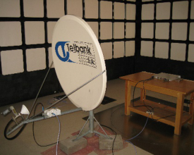
The device under test includes the Paradise Datacom modem, the Prodelin 1134 antenna and the BUC NJTS017L transmitter. During the measurements in the Paradise Datacom modem, the SCPC mode was set and the limiting
258 Przesmycki and Bugaj
Table 1. Sample human systems integration test parameters Uncertainty of measuring the maximum harmonics level for satellite terminals.
Table available in the original PDF paper.
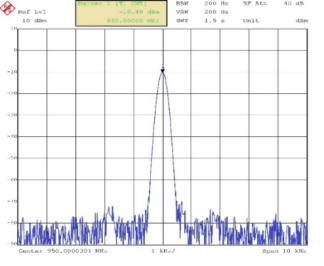
Figure 5: Satellite terminal type PARADISE DATACOM PD10L.Figure 6: Frequency spectrum near the bottom frequency of 900 MHz from the bandwidth range L for the Paradise Datacom mode.
frequencies in its band L range defined in the NO-58-A217:2009 standard were set. The frequency range for the tested modem in the L band is 950 MHz - 2000 MHz. The appearance of the tested satellite terminal is shown in Figure 5.
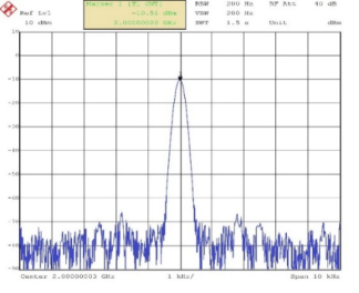
Below in Figure 6 and Figure 7 are presented the results of measurements of the operating frequency band in the basic band for VSAT satellite termi- nals for the PARADISE DATACOM PD10L terminal containing the Paradise Datacom modem.
The Measurement of Baseband Frequency Range for Military Satellite Terminals 259
Figure 7: Frequency spectrum near the upper frequency of 2000 MHz from the bandwidth range L for the Paradise Datacom modem.
CONCLUSION
The article presents a laboratory stand and a method for measuring the ope- rating frequency in the basic band for VSAT satellite terminals, which was developed on the basis of European civil standards and a military standard containing requirements on the operating frequency in the basic band for VSAT. In the case of measuring the operating frequency in the basic band for satellite terminals of the tested device, we must remember to estimate the uncertainty of the measurement. The extended value of the uncertainty of measurement for individual frequency ranges is determined from the f0 ± 2 * 10−7 relationship. For example, for 14 GHz frequencies, the result with an expanded uncertainty of measurement is 14 GHz ± 2 * 10−7.
ACKNOWLEDGMENT
This work was financed by Military University of Technology under research project UGB-22-741/2022 on “Electrical parameters measurement of solid materials using the reflection and the free space method in the millimeter band”.
REFERENCES
EN 60835-1-2:2002 Metody pomiarów urza˛dze´n stosowanych w radiowych mikrofalowych systemach transmisji cyfrowej. Czç´s´c 1–2.: Jednolite metody pomiarów dotycza˛ce systemów linii radiowych i naziemnych stacji satelitarnych. Parametry podstawowe. EN 60835-3-13:2000 Pomiary naziemnych stacji satelitarnych. Systemy VSAT. H. Madiawati and J. Suryana, “Design and implementation of mobile antenna VSAT
with microstrip array based at Ku Band Frequency,” 2016 10th International Conference on Telecommunication Systems Services and Applications (TSSA), Denpasar, 2016, pp. 1–5. doi: 10. 1109/TSSA.2016.7871065 J. M. Kelner, B. Uljasz and L. Nowosielski, “BER measurements in the evaluation of operation correctness of VSAT modem traffic interfaces,” 2018 14th International Conference on Advanced Trends in Radioelecrtronics, Telecom- munications and Computer Engineering (TCSET), Slavske, 2018, pp. 36–40. doi: 10.1109/TCSET.2018.8336151
260 Przesmycki and Bugaj
J. Y. C. Cheah, “Frequency reference in VSAT,” in IEEE Transactions on Communications, vol. 42, no. 234, pp. 233–236, Feb-Apr 1994. doi: 10.1109/TCOMM.1994.577021 M. E. Ilchenko, K. S. Sunduchkov, S. E. Volkov and P. N. Jalandin, “New Resources for the VSAT-Networks,” 2006 16th International Crimean Microwave and Telecommunication Technology, Sevastopol, Crimea, 2006, pp. 315–318. doi: 10.1109/CRMICO.2006.256407 NO-58-A217:2009 Systemy ła˛czno´sci. Wojskowa ła˛czno´s´c satelitarna SHF. Wyma-
gania dotycza˛ce interoperacyjno´sci PN-ETS 300 456:2005 Satellite Earth Stations and Systems (SES); Test methods for Very Small Aperture Terminals (VSATs) operating in the 11/12/14 GHz frequency bands.
Read this individual research paper free through the original publisher, or explore the full digital proceedings book.
ISBN 978-1-958651-44-5
Explore this ISBN in the AHFE Bookstore ↗Listed in the July 2026 bookstore catalogue; search by ISBN to confirm current availability · Digital book purchase optional