Zuo Pianpian, Jiang Jun (2023). Model-based human-machine interaction design of civil aircraft cockpit. In: Human Factors and Systems Interaction. AHFE Open Access, vol. 84, pp. 167–174. https://doi.org/10.54941/ahfe1003602
As aircraft systems become more complex, the cross-links between systems become more and more inseparable. The failure of certain faults can lead to a cascade of failure effects. In order for the crew to quickly locate the fault, quickly isolate the fault in the shortest possible time, and eliminate the impact of the failure, it is necessary to consider the cockpit human-machine interaction design comprehensively. At present, designers mostly analyze the impact of failure based on design documents, and the work is complicated and prone to omissions and errors. Therefore, this paper proposes a model-based human-computer interaction design method for civil aircraft cockpit to help designers quickly conduct cross-system impact analysis, so as to make the design more effective and correct.The overall architecture of the model adopted by the model-based civil aircraft cockpit human-computer interaction design method is mainly divided into the failure state layer, the system function layer and the physical component layer. The failure state layer mainly describes the different failure states of each function of the system, and the correlation between the failure state and the alarm information of the unit. The system functional layer mainly describes the functions of the system and their internal associations, in addition, the functional cross-linking relationships between different systems are also described at this layer. The physical component layer mainly describes the physical components and related physical architecture required for the realization of each function of the system, and correlates the control points and crew alert information that can be controlled by the crew.Since the spread of failure will lead to many alert messages, if the primary message is displayed at the same time as the secondary message, it will be difficult for the crew to quickly determine the true root cause fault and take appropriate countermeasures. Therefore, when designing the crew alert, the designer can analyze the failure propagation through the model, comprehensively consider the cockpit crew alert effect, and avoid excessive alert information and interference with the flight crew.In order to ensure the flight safety of the aircraft, various control devices are designed in the cockpit, which provide a channel for the interaction between the crew and the aircraft system, and facilitate the pilot to adjust the operating state of the aircraft system. When designing the control points, the rationality and effectiveness of the setting of the control points of the crew can be analyzed through the model, so as to reduce the impact of failure as much as possible and avoid excessive load on the crew.Model-based human-computer interaction design method for civil aircraft cockpit takes system functions as the core, supports failure states and physical components, and correlates crew alarm information and control points. This approach can help designers quickly perform cross-system impact analysis, and provide a reference for the design of civil aircraft cockpit crew alarm and control points.
As aircraft systems become more complex, the cross-linking between systems become more and more inseparable. Some faults may lead to a series of failures, resulting in a large number of alerts (Boda, 2016). According to AC25.1322 (Federal Aviation Administration, 2010), in order to enable the crew to quickly locate the fault and understand the fault status of the aircraft, disturbing alerts should be avoided, and important or appropriate alerts should be notified to the crew. At the same time, in order to cut off the pro- pagation of faults, it is also important to set control points reasonably based on redundant system architecture.
At present, designers mostly use design documents to capture alert requi- rements and analyze the impact of failures, which is complicated and prone to omissions and errors. In order to solve this problem, literature (Wu et al., 2020; Xue and Xiao, 2021; Cheng et al., 2019) proposes modeling meth- ods from the aspects of functional operation state, system function model and model-based system engineering, and explores the design method. This paper proposes a model-based human-machine interaction design method for civil aircraft cockpit, which can help designers quickly conduct cross-system failure impact analysis, so as to make the design more effective and correct.
MODEL ARCHITECTURE AND CONSTRUCTION In order for a civil aircraft to perform its intended mission, each system needs to perform its intended function. The implementation of system functions is usually accomplished by a combination of different physical parts, with control points that allow the crew to control the state of the system when necessary. At the same time, different functions have different failure states, and the failure state is the information that the crew needs to focus on, and there is usually a crew alert message to remind the crew. Therefore, the model proposed in this paper takes the system function as the core, takes failure state and physical parts as the support, and correlates the alert information and control points of the crew.
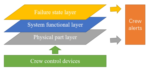
The overall architecture of the model is mainly divided into the failure state layer, the system function layer and the physical part layer. The failure state layer mainly describes the different failure states of each function of the system, and the correlation between the failure state and the alert informa- tion of the crew. The system functional layer mainly describes the functions of the system and their internal associations, in addition, the functional cross- linking relationships between different systems are also described at this layer. The physical part layer mainly describes the physical parts and related phy- sical architecture required for the realization of each function of the system, and correlates the control points and crew alert information. A schematic diagram of the overall architecture of the model is shown in Figure 1.
Figure 1: Schematic diagram of the overall architecture of the model.
MODEL-BASED INTERACTION DESIGN Due to the complex cross-linking relationship between aircraft systems, the effects of some failures can spread to other systems, resulting in cascading failures. Through the above model, we can analyze the path of failure propa- gation according to the initial fault state, and identify the affected functional and physical parts.
The steps for model-based failure broadcast path analysis are as follows: a) Set the failure state or physical part corresponding to the root cause fault to the fault state in the model;
Model-Based Human-Machine Interaction Design of Civil Aircraft Cockpit 169
b) Identify the function corresponding to the root cause failure through the association relationship between the failure state/physical part and the function in the model; c) Identify affected functions through the association between function and function in the model; d) Identify the affected physical parts and failure states through the asso- ciation of functions with failure states and physical parts in the model.
Model-Based Crew Alert Design The fault that can cause a series of other faults is the root fault, and the cor- responding crew alert message is called the primary message, and other faults caused by the root fault are called derivative faults, and the corresponding crew alert message is called secondary message.
The spread of failures can lead to numerous crew alerts. If the primary message is displayed at the same time as the secondary message, it will be difficult for the crew to quickly determine the root fault and take appropri- ate countermeasures. At this time, the cockpit crew alert effects should be comprehensively considered, and the prompts of some alerts in the cockpit should be appropriately suppressed, so that the crew alert can guide the crew to establish comprehensive situational awareness in complex and abnormal conditions in the optimal prompt mode.
The model-based crew alert design steps are as follows: a) Set the function or physical part corresponding to the root cause alert to the fault state, and analyze the failure propagation path through the model; b) Based on the failure propagation path, identify the crew alerts correspon- ding to the affected functions and physical parts; c) Comprehensively analyze the cockpit effect of each crew alert and reaso- nably suppress the excess cockpit effect.
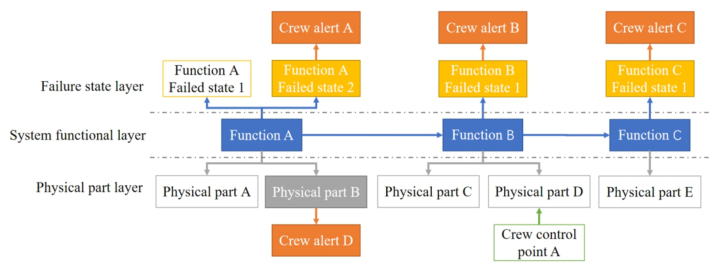
Figure 2 is a schematic diagram of the model-based crew alert design analysis, in which the failure of physical part B causes function A to present a failure state 2, and affects function B, which in turn affects function C, so that function B and C both present their respective failure states 1. Through
Figure 2: Schematic diagram of crew alert analysis.
170 Zuo and Jiang
Table 1. Example of cockpit crew alert effect.
Table available in the original PDF paper.
Crew alert Prompt form Display Lamplight Audio
Single tone (superfluous)
A Character A Master warning light Sustained tone B Character B (superfluous)
Master caution light (superfluous) Voice
C Character C (superfluous)
Master caution light (superfluous) Fault light Single tone (superfluous)
D Character D (superfluous)
the failure state and physical part, the associated crew alert A, B, C, and D can be identified, and an example of the cockpit alert effect when physical part B fails can be identified as shown in Table 1.
Based on aircraft design concept, the cockpit crew alert effect is reasonably designed, and some redundant prompts are suppressed, which can guide the crew to understand the fault status in the optimal form of alert after the physical part B fail.
Model-Based Crew Control Point Design Through the crew alert design, the crew can quickly understand the fault status of the aircraft, in order to ensure the flight safety of the aircraft, the crew also needs to isolate the fault as much as possible and reduce the impact of the failure. Therefore, various control devices are designed in the cockpit, which provide a channel for the interaction between the crew and the aircraft system, and facilitate the crew to adjust the operating state of the aircraft system. The action point of the control device in the system is called the crew control point. The necessity and rationality of the crew control point setting can be analyzed by the model. The model-based crew control point design steps are as follows:
a) Set the function or physical part corresponding to the root cause alert to the fault state, and analyze the failure propagation path through the model; b) Analyze the physical architecture of the system where the affected physi- cal parts on the failure propagation path are located, identify the physical parts that can isolate, mitigate or offset the effects of the failure, set cor- responding control points, and design some control points as automatic control as needed.
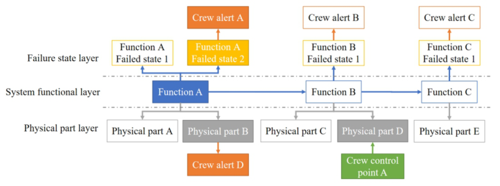
Figure 3 is a schematic of the model-based crew control point design analysis. Each system is typically backed up for its physical parts for critical functions, as shown in physical part D in Figure 3. When function B fails due to function A, backup part D can restore function B to terminate the failure propagation and avoid function C being affected. Therefore, through the analysis of the model, control point A can be set at the backup part D, and when the failure of function A affects function B, the backup part D is manually enabled to terminate the propagation of the failure impact and
Model-Based Human-Machine Interaction Design of Civil Aircraft Cockpit 171
Figure 3: Schematic diagram of control point analysis.
isolate the failure effect; Depending on the degree of automation, this control point can also be set to automatic control on demand. In addition, it is also possible to analyze the control points involved in certain failures based on the model, optimize the location and number of control points, and avoid causing a large workload to the crew while minimizing the impact of failure.
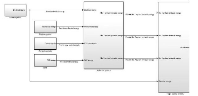
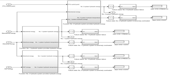
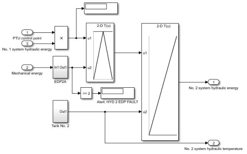
ANALYSIS EXAMPLE Taking the power system, engine system, hydraulic system and flight control system as an example, Figure 4 is the modeling diagram of the functional association relationship between different systems, Figure 5 is the modeling diagram of the relationship between function, failure state and alert, and Figure 6 is the modeling diagram of physical parts.
In the engine function model, the failure state of “loss of provided mech- anical energy” is activated, and through simulation, it can be found that due to the lack of mechanical energy, the mechanical pump of the No. 2 hydraulic system fails (the associated alert “HYD 2 EDP FAULT”), which in turn leads
Figure 4: Schematic diagram of the functional association relationship between diffe- rent systems.
172 Zuo and Jiang
Figure 5: Schematic diagram of the relationship between function, failure state, and alert.Figure 6: Schematic diagram of the physical parts.
to the low pressure of the No. 2 hydraulic system (the associated alert “HYD 2 PRESS LO”). Since the No. 2 hydraulic system has no hydraulic energy output, part of the control surface of the flight control system loses control (associated alert “FCS 1 + 3 SPOILERS FAULT”).
The cockpit alert effects of “HYD 2 EDP FAULT”, “HYD 2 PRESS LO” and “FCS 1 + 3 SPOILERS FAULT” are shown in Table 2.
After comprehensive consideration, the crew needs to realize as soon as possible that there is a problem with the function of “providing hydraulic energy of No. 2 system”, so the crew alert cockpit effect can be designed as follows: a) Prioritize the display of “HYD 2 PRESS LO”, and suppress “HYD 2 EDP FAULT” and “FCS 1+3 SPOILERS FAULT” as needed; b) Master caution light and single tone do not need to be triggered repeatedly; c) The fault light can be retained because it is in the top plate area and does not interfere with the master caution light.
Model-Based Human-Machine Interaction Design of Civil Aircraft Cockpit 173
Table 2. Cockpit crew alert effect.
Table available in the original PDF paper.
Crew alert Prompt form Display Lamplight Audio
Fault light N/A
HYD 2 EDP FAULT
Hydraulic system No. 2 mechanical pump failure
HYD 2 PRESS LO master caution light Single tone
Hydraulic system No. 2 is low pressure
master caution light Single tone
No. 1 and No. 3 spoilers are lost
FCS 1+3 SPOILERS FAULT
Analysis of the physical architecture of the system in which the affected physical parts are located reveals that hydraulic system No. 2 is designed with a PTU (Power Transfer Unit) in addition to a mechanical pump. With PTU, hydraulic system No. 1 can pressurize hydraulic system No. 2, so con- trol points can be designed at PTU. By manually opening the PTU, the No. 2 hydraulic system is pressurized, thus avoiding the user system from being affected. If the workload of the crew is large in this scenario, consider auto- mating the control design of the PTU to cancel the control point and reduce the workload of the crew.
In summary, the model-based human-machine interaction design method of civil aircraft cockpit can quickly analyze the failure impact of cross-system, identify multiple alert triggers, and help designers analyze the comprehensive effect of cockpit crew alerts to avoid excessive alert information and interfe- rence with flight crews. At the same time, it can also help designers identify the requirements of crew control point and automatically control it as needed according to the crew workload.
CONCLUSION
In this paper, a model-based design method for human-machine interaction in the cockpit of civil aircraft is proposed.This method takes system function as the core, takes failure state and physical parts as the support, and correlates crew alerts and control points.Based on the established model, this paper ela- borates the model-based design method of crew alert and control point, and verifies the effectiveness of the method by taking the power system, engine system, hydraulic system and flight control system as examples. The verifica- tion shows that the model-based human-machine interaction design method of civil aircraft cockpit shall help designers quickly analyze the failure impact across systems, and improve the design method of civil aircraft cockpit crew alerts and control points.
REFERENCES
Cheng Z. J., Xiao G., Wu Y. Q., ed. (2019). A method of civil aircraft cockpit integrated alert information modeling and evaluation based on MBSE. In
174 Zuo and Jiang
Proceedings of IEEE Digital Avionics System Conference (DASC). San Diego, USA. pp. 61–68. Federal Aviation Administration. (2010) AC25.1322, FLIGHTCREW ALERTING. Huang Boda. (2016) “Alert Inhibit Design Consideration for Flight Crew Alerting System of Civil Aircraft”, proceedings of the 5th International Forum on Avionics for Civil Aircraft in 2016. pp. 160–166. Wu Y. Q., Xiao G., Wang M. (2020). Cascading failure analysis method of avionics
based on operational process state. IEEE Access. Volume 8: pp. 148425–148444 Xue Z. T., Xiao G. (2021). Research on alarm capture based on hydraulic system model. Civil Aircraft Design and Research. Volume 4: pp. 22–27.
LISTED IN THE AHFE DIGITAL BOOKSTORE CATALOGUE
Explore the complete digital volume
Human Factors and Systems Interaction
Read this individual research paper free through the original publisher, or explore the full digital proceedings book.
ISBN 978-1-958651-60-5
Explore this ISBN in the AHFE Bookstore ↗Listed in the July 2026 bookstore catalogue; search by ISBN to confirm current availability · Digital book purchase optional