Edgar Scherstjanoi, Christiane Kamusella, Daniel Gröllich, Kai Bürkle (2020). Ergotyping®-Tools providing Computer-Based Support for Ergonomic Evaluation Processes of Human-Machine-Interfaces. In: Advances in The Ergonomics in Manufacturing: Managing the Enterprise of the Future. AHFE Open Access, vol. 12. https://doi.org/10.54941/ahfe100467
Faculty of Mechanical Engineering, Institute of Material Handling and Industrial Engineering, Chair of Ergonomics, Technische Universität Dresden, Dresden, 01062, Germany ↗
Ergonomic analysis and assessments help to reveal potential risks for either planned or established working conditions to determine the necessity for further measures. In order to effectively identify the parameters with the biggest impact(s) on improvements in designing or redesigning working environments, it is necessary to extract adequate indicators with major influences on working conditions (Bürkle et al. 2013). This can be done effectively by using computer-based ergonomic tools. Different effects on work related strain become apparent by changing parameters within certain indicators. Alternative workplace designs aiming at changing these parameters can be developed and tested with focus on complying with set requirements. As this procedure is often carried out iteratively, it is obvious that Ergotyping® can help facilitating this process extensively.
To examine ergonomic aspects with computer-aided tools and methods, the Chair of Ergonomics (TU Dresden) introduced “Ergotyping®” as one of the ergonomic components within the process of Digital Prototyping2 (Kamusella; Schmauder 2009). The wording subsumes aspects of ergonomic aspects and prototyping characteristics in terms of Ergotyping®-Tools which are being developed since 2008 (Kamusella 2012b). These tools combine ergonomic knowledge from various regulations, standards and further information deriving from approved ergonomic sources respectively. All tools work with the digital human model (DHM) “Character Animation Tool Ergonomics” (CharAT Ergonomics). CharAT is the core software of the company Virtual Human Engineering (VHE) GmbH Stuttgart3. Constant cooperative research and development between the Chair of Ergonomics of the TU Dresden and the VHE GmbH produce further Ergotyping®-Tools, which are incorporated into CharAT Ergonomics. These tools take national, European and international anthropometric databases and standards into account.
The DHM-based approach benefits from opportunities provided with digital prototypes. Each Ergotyping®-Tool enables creating or re-designing workplaces with interactive possibilities of real-time measurement, assessment and evaluation. Results are displayed in a dynamic monitoring box or on geometrical objects with certain tool-specific 1 Ergotyping is a registered trademark of the Technische Universität Dresden 2 Kamusella: www.ergotyping.net 3 www.virtualhumanengineering.com Ergonomics in Manufacturing (2020) colour coding respectively.
Following chapters are organized to present different Ergotyping®-Tools, illustrated by specific situations.
“Body Forces” allows body force assessments in accordance to the “Force Atlas” and the German standard DIN 33411. It combines this established expertise with the method of calculating reduction factors according to Burandt and Schultetus (Kamusella und Ördögh 2011).
“Visibility” is a tool for visual assessment and visual requirements of optical displays (Kamusella; Schmauder 2010).
“Posture Analysis” handles body posture assessments according to the established methods “Rapid Upper Limb Assessment” (RULA) and “Ovako Working Posture Analysing System” (OWAS) (Kamusella 2012a; Gröllich 20012a; Gröllich 2012b).
“Manual Handling“ assesses the risk for work-related injuries regarding work tasks requiring manual load handling. It incorporates the “Key Indicator Methods (KIM)” for Lifting, Holding and Carrying, developed by the German Federal Institute for Occupational Safety and Health (BAuA).
"BODY FORCES" “Body Forces” assesses force applications to qualitatively pre-estimate or quantitatively evaluate isometric application force of the arm-shoulder-apparatus or the whole body. It also indicates risks for work-related injuries by providing colour encoded feedback. The force evaluation methodology is implemented according to the “Force Atlas for Assembly Operations” (Force Atlas) as well as the information provided with DIN 33411 parts 4 and 5, combined with the method of calculating reduction factors according to Burandt and Schultetus.
By using the following example scenario, an effective usage of “Body Forces” will be explained in more detail: Within an assembly task, a component has to be adjusted vertically and horizontally. The task is designed to be carried out by two male operators. One of them (A) permanently controls the orientation of the component whereas the other one (B) turns adjusting screws using a wrench. The right hand of B is used to apply the required force; B’s left hand is used to position the wrench on the screw and ensuring proper contact. Turning direction and quantity of necessary turns are communicated by A. For this example, the B shall stand on narrow work scaffoldings. By considering the wrench geometry, the required torque results in a force application of 220 Newton.
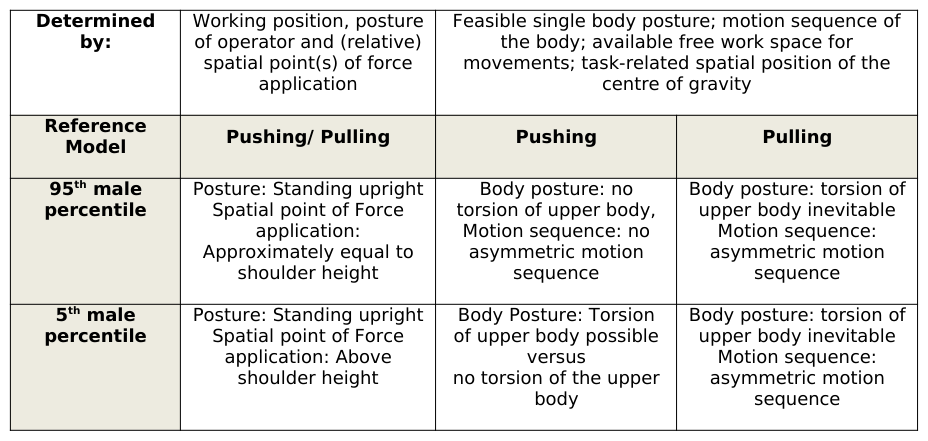
The first step of “Body Force” usage is to reproduce the expected body postures for male operators with their different anthropometric parameters. In this context, the spatial point of force application is essential. The middle of the DHM’s hand is set to match the point for the force application, requiring a specific posture. At this point, the posture is automatically assigned to one of 18 variations according to the Force Atlas. In this example scenario, unfavourable twisted body postures are probable. The operator most likely needs to apply the force standing quite close to the screw position. With respect to the influences deriving from body measurements and force application capabilities, four reference models are taken into consideration. The differentiation of the reference models act in accordance to the requirements stated in the Force Atlas. The method distinguishes between the 5th and the 95th male percentile (DIN 33402) in the age of 50 years (>45 years according to the Force Atlas) and 25 years respectively. In summary, following criteria indicate relevant postures providing a basis for ergonomic assessment of force application corresponding to the Force Atlas (refer table 1).
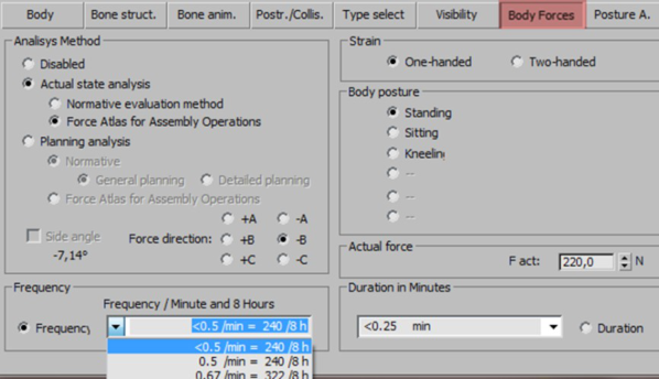
“Body Forces” distinguishes between planning and actual state analysing purposes regarding force percentiles (15th percentile and 50th percentile) and risk assessment sections (DIN EN 1005-3 and ISO 11228-2). Dependant on body postures, the tool dynamically addresses adequate back-frame database entries and compares results of ergonomic assessment for different boundary conditions in real time. Figure 1 shows a dialog for possible input parameters concerning body force assessment.
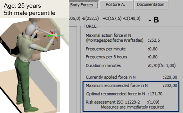
Figure 2 exemplarily demonstrates the results for the 5th male percentile applying a force in the direction of –B for current state analysis with regards to ISO 11228-2.
Table 1: Predictions for anthropometrically determined postures of the DHM for specific force application cases Determined Working position, posture Feasible single body posture; motion sequence of by: of operator and (relative) spatial point(s) of force the body; available free work space for movements; task-related spatial position of the application centre of gravityFigure 1: Input Parameters within “Body Force”Figure 2: Example of the real-time monitoring box for assessing force applications; direction: -B (pushing)
Analysing the body forces for all reference models and application cases reveals that measures are necessary, irrespective of age (25 or 50 years of age) and anthropometrics (5th male to 95th male percentile) for both force directions (pushing and pulling). The risk index shows up between 0.9 (measures required) and 1.21 (measures are immediately required).
The next step is to manipulate adequate parameters which have a major influence on relevant working conditions and whilst monitoring their impact on body force assessment results. For the given example, possible changes might apply for:
avoiding the torsion of the upper body,
enabling a two-handed performing of the task,
changing the relative spatial location of the force application point with regards to the operator’s position,
reducing the necessary amount of force.
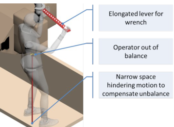
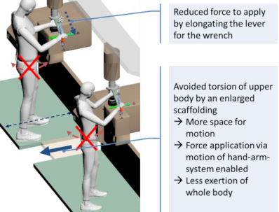
By assuming that the amount of force application efforts is not subject to be changed, the above mentioned influences can now be simulated using the DHM, varying certain parameters. A real-time monitoring box shows how upper body movements and hand-body distances change risk indices dynamically. This approach also helps to consider further aspects. For example if an elongated lever of the wrench can still be handled by a small operator. Another intention might be to reveal physiological or spatial limitations of surroundings as shown in figure 3. Every single modification leads to different maximum or recommended force values. Observing these alterations helps to interactively generate different variants of designing and immediate assessing.
Figure 3: Elongated lever of wrench influencing the body position and motion sequence of a 5th male percentile
Table 2 demonstrates an extract of a comparison for the different parameters regarding their impact for the overall risk indices for both of the force application directions evaluated for the 25 year old reference models.
Table 2: Parameter impact evaluated with the tool “Body Forces”
Table available in the original PDF paper.
Figure 4 shows some of the possible solutions to optimize the task given in the example reducing the risk for work- related injuries. The risk index after re-designing the work task turns out to be significantly lower.
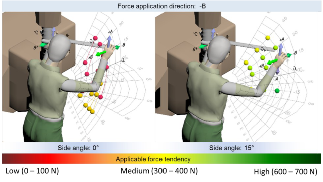
Figure 4: Specific measures to optimize the work design concept for the given example Another fundamental capability of “Body Forces” supports workplace designers during early planning phases. It can be used to estimate tendencies for applicable forces dependant on different fields of reach. This estimation functionality of “Body Forces” differentiates between percentiles, gender, body postures and force application directions. Isodynamic lines, as presented in standard DIN 33411 are incorporated with colour encoded visual elements as illustrated in figure 5. Their spatial positions are described with polar-coordinates, utilized with different layers for azimuth and elevation with shoulder joints as points of origin. Resulting tolerable and risk assessed limits can be obtained directly from each of the elements, providing an interactive insight into applicable forces in early phases of work task planning. The demonstrated situation (two handed force application) in figure 5 reveals that widening the azimuth to 15° for both of the directions (+/- B) has a positive impact. As a result, the position of force application should be arranged more outwards.Figure 5: Example for estimated applicable force tendencies with regards to isodynamic lines provided by the standard DIN 33411 (parts 4, 5) for force application direction -B, showing tendencies for two different azimuth angles
"VISIBILITY" AND "POSTURE ANALYSIS" The tool “Visibility” can be used for virtual view analysis of visual objects, which can be found in machines, plants, measuring instruments, optical displays as well as monitoring consoles. The implementation accommodates user- and product-oriented parameters.
Within “Visibility” the DHM virtually focusses its eyes on a stimulus by a sequential eye-head-body-movement. Therefore, the following criteria can be simulated for various subjects to compare different design variants:
centre of fixation,
position and orientation of the line of sight,
visual collisions dependant on specific body postures.
Additionally, the tool provides support for designing visual information as well as optimal placement and orientation of optical displays. This occurs in consideration of accommodative vergences and age-related visual acuity reduction. The monitoring box shows dynamic feedback about the current state of design and impacts of applied changes.
To establish contact between the line of sight and a visual target, presets for convenient angle limits for the serial eye-head-body-movement for the DHM can be used. In order to fixate a visual object with the line of sight, a gaze- controlling element is implemented. Within convenient viewing angles the DHM simulates eye movements. Exceeding comfortable limits leads the DHM to contacting the visual object by also moving head and torso respectively. It becomes immediately evident should visual objects be placed outside of optimal ranges of movements. The resulting body posture can be evaluated by a further tool specialized in assessing risks for body postures.
“Posture Analysis” evaluates work-related constraint postures and movements. Currently integrated screening methods are “RULA” (Rapid Upper Limb Assessment) and “OWAS” (Ovako Working Posture Analysing System). RULA assesses pre-selected individual postures of the upper arm, forearm, wrist position, head, trunk and lower extremities as well as aspects of muscular effort. OWAS evaluates individual whole-body postures in combination with load handling. Additionally static and dynamic individual postures of the head, arms, legs and trunk can be evaluated time-based.
In the following, ”Visibility” and “Posture Analysis” are explained in detail, using an example: An operator works at a workplace for quality assurance. He has to detect various product data on a screen. Defective products are sorted out and put into a separate box by hand. The assembly line has a fixed height; the position of the screen is fixed. Ergonomics in Manufacturing (2020)
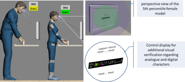
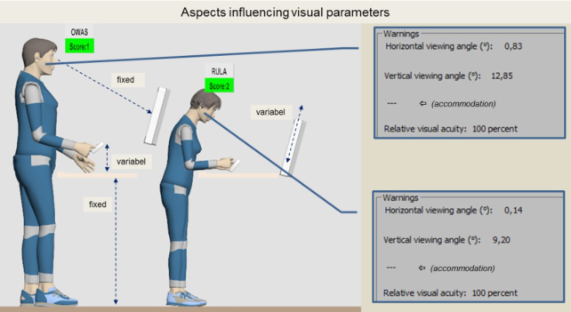
The aspects within this example result in physical strain regarding body posture and geometric parameters for visibility due to the workplace geometry (refer figure 6). By simulating the working sequence, “Posture Analysis” automatically evaluates the postures, depending on the selected method (RULA or OWAS). It quantifies them by a resulting score. OWAS reveals a score colour encoded with yellow for the given example.
Furthermore, “Visibility” shows that the optimal viewing distance is below the limit for elderly people with beginning presbyopia. With regards to medium-visual requirements the specifications for vertical and horizontal viewing angles are below the limit for all users. The deviation might result in parallax errors and distortion of pictured icons.
Another functionality of “Visibility” is the possibility to objectively dimensioning digital and analogue characters on an optical display. Depending on viewing distances between display and eyes, optimal and permitted sizes for digital and analogue characters are calculated dynamically. Furthermore, a view from the perspective of the DHM is possible. The right side of figure 6 shows different fields of view. The green area is the optimal field of vision for fixations. The blue area represents the range of colour vision. Light gray marks the area where bright and dark perception is possible.
For the given example, all visual objects are within the optimal field of vision and the dimension of characters corresponds to stated specifications.
Figure 6: Assessment of the body posture in accordance to OWAS for 95th male percentile and 5th female percentile in combination with aspects of virtual view analyzing samples
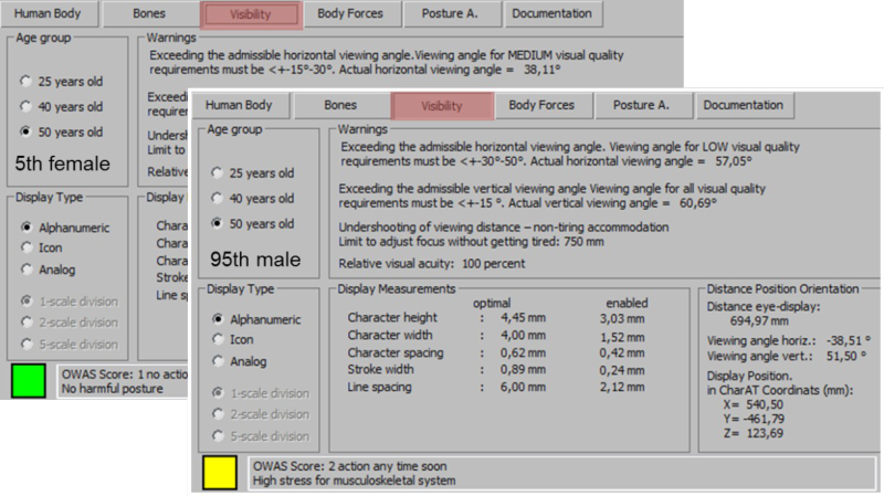
Figure 7 shows the results of the visual evaluation for two reference models in comparison. The results reveal indicators with major influences on vision related to working conditions. The monitoring dialog box shows:
the current viewing distance,
the evaluation with respect to visual acuity,
the evaluation with respect to visual acuity and accommodation for the age group "50 years old",
the characters dimensioning for a selected display type,
vertical and horizontal viewing angles compared to ergonomic requirements.
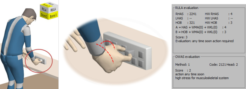
Figure 7: Ergonomic assessment of visual requirements for the 95th male percentile and 5th female percentile “Posture Analysis” for the example “sorting out defective products” reveals that the task basically affects the shoulder and neck area as well as the hand-arm system. Figure 8 exemplarily demonstrates the assessment for the right hand-arm system using the RULA method.
The right part of figure 8 shows a section of the monitoring dialog box for the tool "Posture Analysis". The individual codes of the classification criteria are listed. It reveals physiologically unfavourable flexion in the wrist as well as head and trunk flexion. The analysis of the body posture with OWAS can be displayed simultaneously.
Figure 8: Ergonomic assessment in accordance to RULA and OWAS for the given example An interactive workflow might include designing visual distance, optimal placement or orientation of optical displays. The interdependency between influencing factors for different reference models can be identified immediately. Table 3 shows a summary of the indicators with major influences.Table 3: Assessment and identification of indicators with major influences and their implications
Table available in the original PDF paper.
Both tools help to effectively deduce optimization or planning activities. Figure 9 shows a possible design concept for the given example. Detailed aspects refer to:
the frontal placement of the display to the users eye in a fixed viewing distance to fulfill accommodative requirements,
possibilities for tilting and adjusting the height of the screen to improve the viewing angle and allow the inclination of the head angle,
adjusting the orientation and spatial positioning of the product pallets to improve hand-arm positions and the posture of the upper body (at a fixed height of the assembly line).
Figure 9: Specific measures to optimize the work design concept for the given example "Visibility" and "Posture Analysis" allow simulating single work-related body postures or sequences of movements, represented by an animated DHM in virtual environments.
"MANUAL HANDLING" "Manual Handling" evaluates working processes with load handling according to the Key Indicator Method (KIM), provided by the German Federal Institute for Occupational Safety and Health. More precisely, “Manual Handling” deals with three kinds of manual load handling: lifting, holding and carrying.
Using KIM conventionally requires an observer to assess a work process by his individual estimation of single key indicators such as average load weight, posture and execution conditions. Each of the estimations are mapped to a certain value, summed up and multiplied by a representative value for duration, repetition or distance, respectively. The resulting value indicates the risk for work-related injuries.
“Manual Handling” evaluates a working process of an animated DHM. In contrast to the conventional human- observer approach this tool benefits from extracting necessary features from animated working processes automatically. This is done by partitioning a scene into successive sequences where each of them is a succession of frames with a common significance (i.e. lifting an object from a shelf to another).
For extraction purposes it is necessary to identify the set of relevant sequences with the DHM handling objects of allocated weights, i.e. boxes or tools. Each sequence stores information about the starting time, duration and distance, as well as the actual weight of the handled object, number of repeats, execution conditions and scores for specific postures. Most of those data is derived directly by environment data of the DHM, the underlying 3D application or input values provided by an expert user.
Depending on the gathered duration and distance data, each sequence is labelled as a lifting, holding, or carrying sequence. This labelling is done with following decisions: If a sequence covers a handling through a distance of more than five meters it is labelled as “carrying”. If the distance is less and the duration of a sequence takes more than five seconds it is labelled as “holding”. Finally, if none of the above mentioned cases apply (distance less than five meters and duration less than five seconds) a sequence will be marked as “lifting”.
In contrast to the other sequence data members (distance, duration, weight), posture information cannot be obtained straight forward since the need of a geometrical analysis of relevant bones. Moreover it is necessary to create a method aiming at modelling an appropriate scoring (which is usually done by human observers as suggested by the KIM). “Manual Handling” utilizes a set of angle and length thresholds which leads to a set of mappings from geometrical values to natural language description as specified within the KIM. The following list presents an overview of all relevant criteria and possible values in natural language.
Using such a set, “Manual Handling” allocates a score for all possible postures using the pattern provided by the KIM. An example can be shown as follows, assuming a DHM in a fixed posture: The weight is located "close to the body" and "below shoulders". Furthermore the DHM "bends low" with "no torso rotation".
Obviously the conventional human-based method is highly subjective. Moreover KIM proposes to average each indicator scoring in total, as long as each part of the work processes differs “not much”, which again leads to different results, depending on the individual observer’s understanding.
In this regard “Manual Handling” extends the KIM in two essential aspects. Firstly, it considers each part of the work process separately. For each part, a linear importance in posture and load weight using distance, duration and repetition is used. The aggregation of these parts results in the final score. Secondly, “Manual Handling” adopts a principle for detecting parts of working processes proposed by the Ergonomic Assessment Worksheet (EAWS). Here every preceding or subsequent lifting sequence is merged with a carrying or holding task, if the lifting can be seen as ergonomically equal or better.
Consider the following as an example scenario for which a DHM animation with “Manual Handling” can be used in order to assess important indications.
An employee has to move boxes from one point to another. Picking up each of the boxes requires different postures of the employee. During the carrying he has to stop in order to hold the box for a couple of seconds. After this interruption he can finally deliver the box. Each box has a load weight of 10kg. The distance between the start and the end point is about 10m. This working sequence has to be repeated five times.
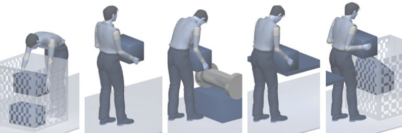
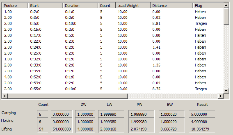
Figure 10 shows the appropriate DHM performing this working process including lifting, carrying and holding. “Manual Handling” automatically fills out the corresponding table for each sequence analysis which can be found in figure 11.
Figure 10: Working sequences: From left to right: Lifting, carrying, holding, transpose (similar to carrying) and lifting.
The application of “Manual Handling” shows that a process under these circumstances would lead to a KIM-score of 5 for carrying and holding, and ~19 for lifting (refer figure 11), which can be interpreted as a scenario where inacceptable high risks are avoided successfully. Usually possible KIM results are between 2 (no risk for work- related injuries) and 80 (need for redesign). It shows that, besides holding and carrying, lifting is the most straining part of this work. Planners should focus on this part of work for the purpose of workplace-design optimization.
Figure 11: Automatic aggregation of sequences shown in figure 10
CONCLUSION
Risks of work-related injuries (and the necessity for countermeasures) are available within a glance. By adjusting adequate parameters interactively using Ergotyping®-Tools, optimization potentials can be identified and appropriate changes to the workplace-design can be implemented effectively.
REFERENCES
Bürkle, Kai; Gröllich, Daniel; Kamusella, Christiane; Köhler, Leonore (2013): Erarbeitung präventiver Gestaltungsansätze zur Reduzierung physischer Belastungen bei der künftigen Rumpffertigung des A350 XWB der Airbus Operations GmbH am Standort Hamburg. Industrieprojekt 2013 Gröllich, Daniel (2012 a): Abschlussbericht zum AIF – ZIM - Kooperationsprojekt „PointCloud-4D – Entwicklung
von Verfahren der automatischen 3D-Bewegungsanalyse auf Basis von 3D-Kameras; Parameterfestlegung aus Ergonomieverfahren zur Bewertung von Körperhaltungen und Verifikation der neuen Technologie“. 2012 – TU Dresden, Arbeitswissenschaft Gröllich, Daniel (2012b): Excel-Makro RULA- und OWAS-Verfahren. Interne ergonomische Arbeitswerkzeuge 2012 Kamusella, Christiane; Schmauder, M. (2009): Ergotyping im rechnerunterstützten Entwicklungs- und
Gestaltungsprozess. In: Zeitschrift für Arbeitswissenschaft, Ausg. 03/2009. Hrsg. Gesellschaft für Arbeitswissenschaft e. V. ISSN 0340-2444, Ergonomia Verlag Stuttgart Kamusella, Christiane; Schmauder, M. (2010): Ergotyping-Tool „Sichtbewertung“. Dokumentation des 56.
Arbeitswissenschaftlichen Kongresses der Gesellschaft für Arbeitswissenschaft in Darmstadt, 24.-26.03.2010, GfA-Press Dortmund 2010, S. 135-138. Kamusella, Christiane; Ördögh, László (2011): Ergotyping-Tool „Körperkräfte“. Dokumentation des 57.
Arbeitswissenschaftlichen Kongresses der Gesellschaft für Arbeitswissenschaft in Darmstadt, 23.-25.03.2011, GfA-Press Dortmund 2011, S. 623-626. Kamusella, Christiane (2012a): Ergotyping®-Tool "Körperhaltungsbewertung". In Dokumentation des 58.
Arbeitswissenschenschaftlichen Kongresses der Gesellschaft für Arbeitswissenschaft in Kassel 22. - 24. 02. 2012 (S. 177-180). Dortmund: GfA-Press. Kamusella, Christiane (2012b): Digitale Ergonomie-Tools zur Berücksichtigung ergonomischer Aspekte im Produktentstehungsprozess in: Stelzer et al.: Entwerfen Entwickeln Erleben. Methoden und Werkzeuge in der Produktentwicklung (10. Gemeinsames Kolloquium Konstruktionstechnik 2012). Dresden: TUDpress Verlag der Wissenschaften. ISBN: 978-3942710800 LV 9 (2001): Handlungsanleitung zur Beurteilung der Arbeitsbedingungen beim Heben und Tragen von Lasten. 4.
überarbeitete Auflage. Hrsg.: Länderausschuss für Arbeitsschutz und Sicherheitstechnik (LASI), 2001.
LISTED IN THE AHFE DIGITAL BOOKSTORE CATALOGUE
Explore the complete digital volume
Advances in The Ergonomics in Manufacturing: Managing the Enterprise of the Future
Read this individual research paper free through the original publisher, or explore the full digital proceedings book.
ISBN 978-1-4951-2103-6
Explore this ISBN in the AHFE Bookstore ↗Listed in the July 2026 bookstore catalogue; search by ISBN to confirm current availability · Digital book purchase optional