Marco Faber, Henning Petruck, Sinem Kuz, Jennifer Bützler, Marcel Ph. Mayer (2020). Flexible and Adaptive Planning forHuman-Robot Interaction inSelf-Optimizing Assembly Cells. In: Advances in The Ergonomics in Manufacturing: Managing the Enterprise of the Future. AHFE Open Access, vol. 12. https://doi.org/10.54941/ahfe100461
Due to an increasing diversity of products in product space production systems have to react more flexible and dynamic. Thereby, the human operator must be seen as an integral part of the production process because on the one hand he/she has to supervise the machines and robots and on the other hand he/she has to take over individual operations that cannot be automated. For establishing a flexible planning process of assembly operations that satisfies also the ergonomic requirements of human-robot interaction a comprehensive Cognitive Simulation Model is presented consisting of a formerly developed Cognitive Control Unit (CCU) and a newly developed graph-based planner. The CCU is based on the popular architecture of human cognition Soar. The additional planner enables the CCU to consider more complex planning criteria regarding the whole assembly sequence. Therefore, the final product is decomposed to obtain all valid assembly sequences and transferred into a state graph. The edges are rated at runtime according to the activated procedural knowledge. A modified version of the search algorithm A*Prune is finally applied to find the best continuations for the current assembly sequence. The presented approach is validated by means of a simulation study. The results show that the human-robot cooperation can be improved significantly, for example, by reducing the number of strenuous manual interventions of the human operator.
Against the background of the rapidly changing demand, manufacturing companies are faced with new challenges. The typical mass production of the second industrial revolution shaped by Frederick Winslow Taylor is more and more replaced by customer individualized production coming with a growth of variety in product space (Wiendahl et al., 2007). Indeed, there may be fewer products, but the number of variants of a single product increases because of individual requirements. In addition, not only the diversity in product space but also the rapidly advancing automation technologies make the planning process for the assembly of a product more complex.
Companies have to cope with these new challenges in order to stay competitive. Designing a more flexible assembly system is one approach. Instead of planning each detail beforehand, the system must be able to find solutions dynamically. Such reactive systems can, if necessary, adjust flexibly to changing conditions of the Ergonomics in Manufacturing (2020) environment. But as soon as several systems have to work together to solve a problem, following only their own internal goals may not lead to an optimal solution. Indeed, each machine would then work in an optimal manner (e.g. considering the wear and tear), but the whole production system may operate at a suboptimal working point since local optima do not necessarily induce a global optimum. However, there are some tolerances in which the machines are able to operate in the vicinity of the optimum so that global goals can be achieved in a better way. Hence, assembly systems benefit from a set of global constraints in order to find a satisfying global solution. Despite of allowing a limited scope of action for the individual systems they are able to find an appropriate local solution and to adjust to the local conditions of the production process.
New technologies in the field of industrial robots enable not only a flexibly automated production but also allows for human-robot cooperation. Especially in high-wage countries having a high educational level, the human operator provides a huge potential for improving the production process of varying products. He/she is able to dynamically adapt to new situations and tasks that cannot be automated (e.g. handling of flexible components) or are not worth to automate due to a small number of repetitions can be taken over. Thereby, the human operator benefits from his/her sensorimotor capabilities and his/her ability of creative thinking so that he/she is able to solve complex and ill-posed problems with quite few data points (Faber et al., 2013a).
However, the involvement of the human being makes high demands on the assembly system and the human- robot interaction. To establish a safe and trustful relationship between the human and the machine, the design of the system should follow the principles of control systems including observability, controllability and predictability (Kalman, 1960; Christofferson and Woods, 2002). In other words, the human operator should be able to comprehend the current system state at any time and to predict the next steps of the automation. This is essential in order to be able to intervene in the automated process whenever it is necessary. To satisfy these conditions the decisions and actions of the automated assembly system should be conform to the expectations of the human operator. This can be achieved by basing the decision making process on knowledge that corresponds to the operator’s knowledge (Faber et al., 2013a). Otherwise, situations may occur that endanger the operator and his/her health.
COGNITIVE SIMULATION MODEL To cope with the challenges of changing demands of assembly systems, as a first step, a comprehensive Cognitive Simulation Model (CSM) has been developed (Faber et al., 2013b). Its design focuses on providing a simplified, compatible representation of the mental model of the human operator about assembly processes in a dynamic production environment. By making the assembly process more transparent the human operator is enabled to relate to the production flow. This is essential not only for understanding the system but also for handling error situations and anticipating the behavior of the system (Kuz et al., 2012; Odenthal et al., 2012).
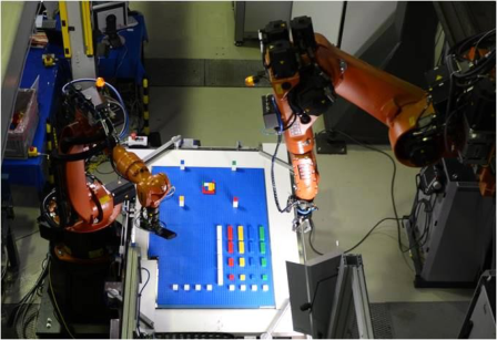
The architecture of the CSM as depicted in Figure 1 provides perceptual interfaces for human-machine interaction and technical interfaces for controlling robots of a robotic assembly cell. The core component is the Cognitive Control Unit (CCU) which is mainly responsible for planning the action sequences of the production process. The human operator interacts with the CCU by means of the human-machine interface in order to change, for instance, the current planning criteria. The technical layer is responsible for controlling the robotic assembly cell shown in Figure 1 (Brecher et al., 2012). The assembly cell consists of an articulated KUKA robot with six axes and a three finger gripper with haptic sensors for assembling components. The workplace is divided into two areas, an assembly area and a buffer store in which parts can be kept for later usage. The supply of the components is realized by means of a circular conveyor belt. Finally, the simulation module of the CSM provides automated access to the CCU, for example, for testing new assembly strategies or the assembly of new components.
Conceptually, the CCU is based on the three layer architecture for robotic applications by Russel and Norvig (2003) comprising a planning layer, a coordination layer and a reactive layer. For simulating the human cognition it has been realized by means of the popular cognitive architecture Soar1 (Laird, 2012). Unlike other methods such as 1 http://sitemaker.umich.edu/soar Ergonomics in Manufacturing (2020)
Human-machine interface Control interface Visualization
Knowledge base
Simulation module Cognitive Control Unit
(CCU)
Technical layer Assembly cell Simulation
Figure 1. Architecture of the Cognitive Simulation Model (left) and controlled robotic assembly cell (right).
(Adapted from Faber et al. (2013b) and Brecher et al. (2012))
neural networks, Soar does not need any training data for instantiation which is favorable especially for dynamic production environments. It uses two explicit input and output interfaces for communicating with its environment. In the context of the CSM the input interface collects sensor data of the production environment whereas commands for the robots are given to the output interface. The planning and decision procedure of Soar is based on human cognition by iteratively running through four phases: (1) The current situation is analyzed and sensor data is collected. (2) Dependent on the current situation action alternatives are identified. (3) The alternatives are traded off against each other and, finally, one preferred action is selected. This decision depends on the embedded production rules. (4) The CCU performs the chosen action, i.e. the corresponding command is given to the environment through the output interface.
As stated above, the decision making process of Soar is based on the embedded knowledge which is encoded in terms of explicit if-then production rules. In the CSM the knowledge base was designed to the end that the assembly process gets more transparent for the human operator who interacts with the system. Therefore, different levels of knowledge have been integrated. The basic knowledge is knowledge that is necessary for being able to assemble a product. It states that a component can only be built if all of its bottom neighbors have already been built. This restriction is reasoned in the application scenario of a robotic assembly cell where the direction of positioning is from above (Brecher et al., 2012). For the second level, the actions that can be chosen by the decision unit of the CCU are based on the fundamental movements of the finger, hand and arm system of Methods Time Measurement (MTM), a predetermined motion times system for analyzing and planning human work in assembly systems. They comprise REACH (including rotation), GRASP, MOVE (including rotation), POSITION and RELEASE so that these motions should agree with the expectations of the human operator. Finally, as a third step, human-like assembly strategies were identified in empirical studies (Mayer, 2012a). Both the basic motions according to MTM and the human-like assembly strategies have been encoded in production rules which can be activated on demand. Combining all three levels, the application of this knowledge base increases the transparency of the production process for the human operator significantly (Mayer and Schlick, 2012b).
However, although the CSM as described above already comprises a lot of rules in the knowledge base, they are still not sufficient for complex assembly processes. Due to the RETE algorithm underlying the process of decision making in Soar, the CCU suffers from an exponential worst-case runtime behavior. This is especially the case when many uniform components could be assembled at the same time assuming that all needed components are available (Mayer et al., 2012c). Besides that, the CCU has a planning depth of only one assembly step, i.e. the planning alternatives are severely limited regarding the whole assembly process. As a consequence, more complex planning criteria involving more than one assembly step cannot be considered adequately so that the course of the assembly sequence highly depends on the next chosen step. In view of human-robot interaction this can lead into dangerous Ergonomics in Manufacturing (2020)
Human-machine interface Control interface Visualization Knowledge base
Simulation module Cognitive Control Unit
(CCU)
Graph-based planner
Technical layer Assembly cell Simulation
Figure 2. Architecture of the Cognitive Simulation Model (CSM) extended with the graph-based planning instance. (Adapted from Faber et al (2013b)) situations for the human operator which cannot be foreseen by the CCU. For efficient human-robot interaction, for example, the planning system must know human skills and capabilities in order to estimate which tasks can be done by the human and which situations should be avoided because they are not acceptable or even harmful. But increasing the planning depth of the CCU would significantly increase the complexity of planning so that the real- time capability of the CCU is impaired for complex products. On the other hand, planning each step beforehand is not feasible as well any longer due to the increasing diversity in product space. To overcome these disadvantages the CCU has been extended by an additional planning system as described in the next section.
Figure available in the original PDF paper.
HYBRID PLANNING FOR HUMAN-ROBOT INTERACTION The limitations of the CCU described in the previous section concerning the planning process necessitate the extension of the planning procedure. However, extending the planning procedure within Soar itself is rather difficult as the problem space for decision making would become very complex. The CCU would have to simulate numerous assembly sequences in order to evaluate complex planning criteria and to find the assembly step fitting best to the current system state.
As a consequence, the CCU has been extended seamlessly by an external graph-based planner. The approach adopts the idea of Ewert (2012) by dividing the planning process in an offline and an online part. In preparation of the production process a state graph is initially generated representing all valid assembly sequences of the product. This graph has to be redesigned only when the product specifications changes and serves as basis for further planning activities. During the assembly process, the edges of the graph are weighted by penalty costs. After that, the costs of all possible next assembly steps are evaluated by means of applying graph search algorithms. The resulting hierarchy of assembly possibilities is given as input to the original planning instance of the CCU. The integration of the graph-based planner into the CSM is depicted in Figure 2.
Generation of the state graph The generation of the directed state graph follows an assembly by disassembly strategy (Thomas and Wahl, 2001). Therefore, only the geometric information about the final product including the position and orientation of the individual components is necessary. Hence, an arbitrary CAD file is sufficient as input for the planning process. The
Ergonomics in Manufacturing (2020)
[Equation or mathematical symbol available in the original paper PDF]
1 2 3 4
3-4 2-4 1-3 1-2 1-4 2-3
2-3-4 1-3-4 1-2-4 1-2-3
1-2-3-4
5 3 4
1 2 1 2
Figure 3. Exemplary state graph for a product consisting of five cubic components. The dotted edges denote assembly steps that have to be taken over by the human operator as these components t b d b t fi i neighborhood relationships between the components are necessary to build the product so that they are extracted using analytical methods based on the CAD data. To generate the state graph all valid assembly sequences have to be identified, i.e. all sequences in which the components can be built one after the other. This is done by recursively decomposing the final product. In particular, those components that do not have any neighbors above are removed. This decomposition yields, the other way around, a valid assembly step only if all bottom neighbors are already present on the workplace. This condition corresponds to the first level of knowledge introduced into the CCU. Each subcomponent resulting from the decomposition procedure represents a valid intermediate state of the product and thereby a node in the state graph. Two states are considered to be equivalent if they contain exactly the same components. Equivalent states are combined to one single node in the state graph.
Figure available in the original PDF paper.
All outgoing edges of a node represent possible assembly steps, i.e. an edge s1→s2 between two nodes s1 and s2 of the state graph is introduced if and only if s2 can be built from s1 by assembling one single component. In the course of the planning process (see below) the edges are rated with penalty costs indicating how expensive it is to perform the corresponding assembly step. Thereby, the higher the costs the more planning criteria are violated. Figure 3 shows an exemplary state graph of a product consisting of simple cubic components. The numbers in the states indicates the components that have been built yet. This graph is reusable for a variety of planning procedures as long as the geometric structure of the final product and its components do not change. The dynamic rating of the edges facilitates adapting the graph to the specific system state.
Calculation of penalty costs The penalty costs of an assembly sequence are determined by means of the weights associated with the corresponding edges. As the weights are adjusted with respect to the current system state, the calculation of the costs must be done at runtime in each planning cycle. Therefore, rules representing the planning criteria can be specified in the knowledge base. Reasons for such rules are, for instance, technical constraints that require leaving two opposite sides of components free to be available to grasp them by means of a two finger gripper. Other rules may concern the interaction of the human operator with the system by penalizing the changeover of the assembly control from the robot to the human operator. Hereby, it is also important to keep the number of changes small. But on the other hand operations that are dangerous for the human must be avoided yielding a possibly higher total amount of changeovers.
Ergonomics in Manufacturing (2020) s0→⋯→ ⏟ si+ j+1→⋯→sn ⏟ si→⋯→si+ j→ ⏟ not considered not available available components components ⏟ basic costs+penalty costs
Fi 4 C l l ti f th t f bit th (s t d s t d s fi l d ) Starting from the current node of the state graph the costs for all successors are determined. Therefore, each rule is tested whether its conditions are violated. If so, there are two cases: In the case that it is allowed to violate the planning criteria (i.e. this assembly step is just made more expensive) the penalty costs are added to the current edge costs. Otherwise, if the rule must never be violated, the assembly step is removed from the set of candidates. The latter case is important for rules representing technical constraints that cannot be omitted whereas the former case allows for ordering the assembly steps according to the favored preferences. The presented procedure for calculating the costs of an edge is repeated for all reachable nodes in the state graph. In the exemplary graph depicted in Figure 3 all solid edges are rated with the same basic costs cb induced by the assembly of an additional component. The dotted edges indicate the assembly steps that cannot be performed by a two finger gripper as there are no two opposite sides that are left free to grasp. Consequently, these edges are rated in addition to cb with the costs c H for a manual assembly step by the human operator. Obviously, there is no possibility to assemble the product without the help of the human being. But the number of interventions can be minimized by selecting the appropriate assembly sequence.
Figure 4 depicts an arbitrary assembly sequence whereas s0 denotes the initial state where no component has been built yet and sn the final state containing all components of the final product. Each edge su→sv (i≤u,v ≤n) is rated with the basic costs cb. Afterwards, the costs caused by the specified planning criteria are added. For evaluating the costs of an assembly step, not only the cost of the outgoing edge but also the total costs of the resulting assembly sequence are important since they are used to rank the alternatives. To calculate these costs a graph search (see below) is performed starting from the current node si. For determining the costs for the total assembly path, it is essential which components are available to be built. Let j be the number of available components. Then, only the assembly steps si+1,…,si+ j can be planned reliably. Nevertheless, for determining the costs of an assembly sequence the edge costs of all remaining assembly steps are summed up assuming that all components required for realizing the optimal path are available when reaching the nodes si+ j+1,…,sn. Certainly,
this is a rigorous assumption because for the purpose of planning all successive nodes are fixed already in si disregarding future situations. But neglecting all none-basic costs in those states could let the planner underestimate the costs of a path such as in the case that all possible assembly steps in si+ j are extremely expensive. Hence, the above assumption has been made because usually the number of remaining steps n−(i+ j) that cannot be planned in detail is much higher than the number of available components. Consequently, the remaining subsequence si+ j+1, …,sn is more important for finding the optimal assembly sequences.
Evaluation of assembly processes The graph-based planning system aims at reducing the solution space for the CCU. Therefore, the planner is involved in each planning cycle during runtime. If the CCU is not busy in terms of assembling a component the graph-based planner is updated with the current system state including the currently built components and the available components. After identifying the current node in the state graph the penalty costs of the successive nodes are updated as described in the previous section.
The evaluation of possible extensions of the current assembly sequence is thereupon done by applying a modified version of the algorithm A*Prune (Liu and Ramakrishnan, 2001). The search strategy of A*Prune follows the one of the popular graph search algorithm A* except that not only the best path is returned but the best k paths. Additionally, a proper tuning technique keeps the set of candidates for these paths minimal. A*Prune is suitable to solve the K Multiple-Constrained-Shortest-Path (KMCSP) problem where each link between two nodes is associated with r constraints. All k paths returned by the algorithm have to satisfy the externally given thresholds of these Ergonomics in Manufacturing (2020) constraints. As the planner described in this paper makes only use of the costs as constraints between two assembly states, the problem is reduced to the K Shortest-Path (KSP) problem. Nevertheless, A*Prune is more efficient for this problem than multiple runs of the original algorithm A* (Liu and Ramakrishnan, 2001).
To adopt the evaluation of the costs to the assembly planning process, two major modifications have been made concerning A*Prune. First, the evaluation of two competitive nodes does not rely only on the costs induced by the basic assembly costs and the penalty costs. Due to the way the family of A* algorithms works the costs of not- available links between two nodes have to be set to infinity. But consequently, the target state would not be reachable any longer for this path so that this path would be removed from the set of candidates for the best k paths. To overcome this effect nodes are first compared by means of the reachable progress in the assembly process that can be realized when selecting that node. The node si is considered to be better than s j if a higher assembly progress can be reached when selecting si. If both nodes cannot be distinguished using the assembly progress, the costs for the remaining assembly sequence resulting from the original A*Prune are compared. Hereby, lower costs give higher preference to a node. Only if both the reachable assembly progress and the costs cannot distinguish two nodes they are compared additionally by means of the reached assembly progress up to the current state. Choosing the node containing more components that have already been built reduces the number of iterations to find the solution. If all three comparisons fail the nodes are considered to be equivalent.
The second modification of A*Prune affects the set of possible next assembly steps returned by the planning system. As each step represents the beginning of the continuation of the current assembly sequence they should preferably be diverse to avoid multiple equivalent solutions. Therefore, multiple paths beginning with the same component are reduced to one single path in the sense that only the best path is chosen to be returned. For being able to make this decision A*Prune has been adjusted so that a second equivalent path from si to s j having a different beginning is stored for later usage.
Finally, the returned set of possible next assembly steps is presented to the original planning instance of the CCU by assigning preferences corresponding to the path costs to the proposed actions. In particular, assembly steps causing high costs are rated with a low probability and vice versa. The CCU can additionally apply a threshold to the path costs in order to neglect solutions deviating too much from the optimal solution. Because of the limited planning horizon of the CCU actions that are considered to be not feasible by the graph-based planner could be proposed by the CCU. These proposals are rejected as the external planner has more information available for the planning process. With the help of the external preferences the CCU proceeds with its normal decision making process and selects that operation considered to be the best based on the internal knowledge. Thereby, it retains its cognitive features and is still able to react dynamically to changes in its environment.
SYSTEM EVALUATION The extended CSM has been evaluated by means of a simulation based study. Besides the correctness of the graph- based planner the study focuses on supporting human-robot cooperation in assembly tasks. Therefore, runtime behavior was evaluated as well as characteristic variables of the assembly process.
Design In the present simulation study the examined factors were the size of the product, the complexity of the state graph, the type of component supply and the number of supplied components. Different monochrome models consisting of cubic components were assembled. Their sizes were varied between 4 and 24 components with step size 4 and their complexity in five steps between 1 and 5 resulting in total in 30 different models. The complexity was determined by means of the average node degree of the corresponding state graph in order to cover a wide area of characteristics in the structure of the model. Models of type 1 consist of one layer whereas all components form a closed plane resulting in a high average node degree. In contrast, in models of type 5 there is only one component per layer yielding a tower of components and a single assembly path in the state graph. The other types in between represent
Ergonomics in Manufacturing (2020)
10 8
10 6
10 5
10 6
10 4
10 4
10 3
number of nodes
generation time [ms]
10 2
10 2
4 8 12 16 20 24 10 0
4 8 12 16 20 24 10 1
product size
product size
Figure 5. Number of nodes (left) and time (right) needed to generate the state graph for the graphintermediate states in which the components are distributed among two or three layers. This composition of the models to be assembled was chosen in order to obtain comparable results with the studies of Mayer et al. (2011) and Mayer (2012a). Besides the model structure the component supply was varied. First, a deterministic supply was chosen, i.e. the components were fed in the order needed to build the product. In contrast, the stochastic supply fed the components in an arbitrary order which could also contain components that were not needed for the current assembly process. The number of components supplied at the same time was varied between 1 and 24.
Figure available in the original PDF paper.
For each combination of the above mentioned factor levels simulations were run using the original CCU and the CCU extended by the graph-based planner. The state graphs of all models needed for the planning process were generated beforehand. The present study focused on two conditions regarding the activated knowledge:
1. The only rule influencing the assembly behavior expresses that components are allowed to be built only next to other components. The human operator is not involved in this scenario.
2. In addition to the rule of the first scenario a second rather technical rule was applied: A component can only be built autonomously if two opposite sides are directly accessible by the robot gripper. This requirement is based in the technical restriction of a two finger gripper. Individual components that do not satisfy this requirement must be assembled manually by the human operator (also simulated by the computer in this study).
Dependent variables for all simulation runs were the time needed for the planning process in the CCU and the graph-based planner, respectively. In addition, the actual assembly sequence including necessary manual assembly actions were collected. The simulations were run on the compute cluster of RWTH Aachen University with up to 32 GB of main memory.
Results
Due to the combinatorial number of variants of the assembly process the number of nodes of the state graph grows exponentially with the size of the model as depicted in Figure 5. Even small models results in large graphs whereas models of type 1 (all components in one plane) have the largest and those of type 5 (all components in a tower) the fewest number of states. The time needed to generate the state graph scales exponentially with product size. This can be explained by the nature of the state graph because nodes containing the same set of built components are combined to a single state. Consequently, larger graphs require a higher overhead for maintaining the set of nodes than smaller graphs.
The products were assembled correctly in all simulation runs. The overall runtime behavior of the CCU (see Figure 6) corresponds with the trend observed in Mayer et al. (2011). The time needed to assemble the model grows exponentially with the size of the model and the number of supplied components when all components are fed in the right order. This effect is mainly caused by the algorithms underlying the cognitive architecture Soar. As each available component is proposed to be built at each possible position in the target state the number of action Ergonomics in Manufacturing (2020) alternatives and consequently the effort to balance them against each other grows exponentially. When feeding the components in an arbitrary manner (possibly containing parts that are not needed) the time grows exponentially only with the number of components in the model. The number of fed components has almost no effect.
When activating the graph-based planner for the case of deterministic supply the total processor time increases, especially with larger numbers of fed components and increasing model size. The convergence of the growth for the cases where the number of supplied components is higher than the model size can be explained by the planning procedure of the graph-based planner. The assembly sequence is planned in detail for as much steps as there are components available. However, if there are more components available than needed the additional components are not taken into account by the planner so that the planning effort remains the same. In the case of a stochastic supply the number of fed components has the same effect as for the original CCU, but the processor time is generally higher than without the graph-based planner.
In the second scenario the human operator is directly taken into account because he/she has to manually assemble all components that cannot be processed autonomously. The number of manual assembly steps could be reduced significantly when activating the graph-based planner (F (1,27)=46.420, p<0.05). A significant reduction could also achieved with respect to the model size (F (1.013,27.361)=302.165, p<0.05) which traces back to the structure of the models. The larger the model the more components have to be assembled potentially by the human operator. Figure 7 depicts the average number of manual steps as a function of the model size. The models of size 4 and type 5 (all components in a tower) have been excluded from the analysis as they do not need any human intervention at all. The average number of manual assembly steps could be reduced up to 79.7% of the original number. Regarding the occurrence of the manual assembly steps over time (see Figure 7) it can be observed that the human operator is generally involved later and the time variance is lower. For the models of size 8 and 16 the time of interaction is even reduced to almost a single position in the assembly sequence.
Ergonomics in Manufacturing (2020)
CCU with graph-based planner (deterministic supply)
CCU with graph-based planner (stochastic supply)
Figure 7. Average number of manual assembly steps without and with the graph-based planner (left) and temporal position of the human-robot interaction in the assembly sequence of model type 2 (right).
Figure available in the original PDF paper.
10 0
processor time [s]
processor time [s]
10 0
16
16
12
12
8
8
4
4
1 4 8 12 16 20 24
1 4 8 12 16 20 24
model size
model size
f eeding size
f eeding size
Figure 6. Average assembly time for the original CCU (top row) and the extended CCU (bottom row) with deterministic (left) and stochastic (right) supply as a function of the model size and the number of fed
Figure available in the original PDF paper.
SUMMARY AND OUTLOOK The CSM described in Faber et al. (2013b) has been designed against the background of the changing demands of the globalized world economy in order to control a robotized assembly cell. On the one hand it is capable to react flexibly to changing conditions in the production; on the other hand the human operator is enabled to anticipate the behavior of the automated system at any time because the decision making process is designed to be conform with the human operator’s expectations. However, there still exist tasks such as the assembly of flexible or fragile components which cannot be automated sufficiently and are therefore taken over by the human. His/her excellent mental and sensorimotor skills probably can neither be transferred to automated system in the near future. But in combination with new evolving technologies human-robot cooperation could close this gap. By means of this cooperation the advantages of both the highly productive robot and the flexible, well qualified human being can be used effectively.
In order to introduce the support for human-robot cooperation the CCU has been extended by a graph-based planning system. Thereby, the CSM is able to consider more complex planning criteria that require, for instance, the knowledge of the whole assembly sequence. In addition, ergonomic requirements can be realized by specifying constraints for the assembly process of single components. The CSM is consequently enabled to consider the needs of the human operator while still retaining the flexibility of the CCU.
The graph-based planner works on a state graph containing all valid assembly sequences. This graph is Ergonomics in Manufacturing (2020) constructed once for each product by applying an assembly by disassembly strategy (Thomas and Wahl, 2001). The presented simulation study showed that already for small models the corresponding graph gets very large. The structure of the model influences the size of the graph most as multiple equivalent assembly possibilities let grow the graph exponentially. Regarding the time needed for generating the graph, this is acceptable because the generation is done only once for each product. However, for practical implementation the number of nodes required to represent all valid assembly sequences yields problems regarding the necessary amount of main memory. More efficient solutions are needed in order to cope with larger models such as reducing the number of nodes in the state graph. On the contrary, the necessary set of nodes could also be generated at runtime.
After generating the state graph of the product the graph-based planner is involved in each assembly step of the CCU. The current system state including the components already built and the available components are identified and the next possible assembly steps are evaluated. Therefore, the edges of the state graph are rated according to the activated planning knowledge. The more criteria are violated the higher the costs. The best k continuations of the current assembly sequence are searched by means of the algorithm A*Prune (Liu and Ramakrishnan, 2001) and provided with the corresponding weights to the CCU. Based on the transferred planning knowledge the CCU is then able to decide for assembly steps that satisfy both the global optimization criteria of the graph-based planner and the local flexible optimization of the CCU. However, the processor time increases significantly when activating the planner. This is partially caused by the number of nodes of the graph so that a state space reduction may be helpful. By rejecting or combining more states during the generation of the graph the search space could be reduced considerably. But at the same time information gets lost if, for example, successors of the current state with equivalent assembly steps (e.g., assembling the same type of component) are combined to one single state. Therefore, a tradeoff would be necessary between the level of details and the performance.
Finally, the presented simulation study has shown that by means of the graph-based planner the conditions for human-robot cooperation can be improved significantly. Technical as well as ergonomic constraints for the human operator can be considered in the planning procedure. The number of changes between the human and the robot could exemplarily be reduced, but further constraints are conceivable and realizable. The fact that the absolute reduction of the number of changes is not very high is reasoned in the size and the structure of the chosen models. When considering larger, more realistic models and more constraints concerning the human operator there may be more potential for optimization in the planning procedure of the CSM.
Although the current implementation of the graph-based planner has shown that there is still potential for optimization, the goal of supporting human-robot cooperation could be satisfied. By providing the CCU with an external planning system having a larger planning horizon the CCU is able to adjust more appropriately to the needs of the human operator.
ACKNOWLEDGEMENT
The authors would like to thank the German Research Foundation DFG for the kind support within the Cluster of Excellence “Integrative Production Technology for High-Wage Countries”.
REFERENCES
Brecher, C., Müller, S., Faber, M. & Herfs, W. (2012). Design and Implementation of a Comprehensible Cognitive Assembly System. USA Publishing: Conference Proceedings of the 4th International Conference on Applied Human Factors and Ergonomics (AHFE). Christofferson, K. & Woods, D. D. (2002). How to make automated systems team players. Advances in Human Performance and
Cognitive Engineering Research. Vol. 2, p. 1-12 Ewert, D. (2013). Adaptive Ablaufplanung für die Fertigung in der Factory of the Future (in German). PhD thesis, RWTH Aachen University. Faber, M., Mayer, M. P. & Schlick, C. M. (2013a). Requirements for Modeling the Human Operator in Socio-Technical
Production Systems. The 11th International Symposium on Measurement Technology and Intelligent Instruments. Faber, M., Kuz, S., Mayer, M. P. & Schlick, C. M. (2013b). Design and Implementation of a Cognitive Simulation Model for Ergonomics in Manufacturing (2020)
Robotic Assembly Cells. Springer Berlin Heidelberg: Engineering Psychology and Cognitive Ergonomics. Understanding Human Cognition. p. 205-214 Kalman, R. E. (1960). On the general theory of control systems. Proceedings of the First IFAC Congress, Moscow. p. 481-492 Kuz, S., Heinicke, A., Schwichtenhövel, D., Mayer, M. & Schlick, C. (2012). The Effect of Anthropomorphic Movements of Assembly Robots on Human Prediction. Advances in Ergonomics in Manufacturing. p. 263-271 Laird, J. E. (2012). The Soar Cognitive Architecture. MIT Press. Liu, G. & Ramakrishnan, K. (2001). A*Prune: an algorithm for finding K shortest paths subject to multiple constraints.
Proceedings of the 20th Annual Joint Conference of the IEEE Computer and Communications Societies. p. 743-749 Mayer, M. P., Schlick, C. M., Ewert, D., Behnen, D., Kuz, S., Odenthal, B. & Kausch, B. (2011). Automation of robotic assembly processes on the basis of an architecture of human cognition. Production Engineering Research and Development. Mayer, M. P. (2012a). Entwicklung eines kognitionsergonomischen Konzeptes und eines Simulationssystems für die
robotergestützte Montage (in German). PhD thesis, RWTH Aachen University. Mayer, M. P. & Schlick, C. M. (2012b). Improving operator’s conformity with expectations in a cognitively automated assembly cell using human heuristics. USA Publishing: Conference Proceedings of the 4th International Conference on Applied Human Factors and Ergonomics (AHFE). p. 1263-1272 Mayer, M. P., Odenthal, B., Faber, M. & Schlick, C. M. (2012c). Cognitively Automated Assembly Processes: A Simulation
Based Evaluation of Performance. Work: A Journal of Prevention, Assessment and Rehabilitation - IEA 2012: 18th World congress on Ergonomics - Designing a sustainable future. p. 3449-3454 Odenthal, B., Mayer, M., Kabuß, W. & Schlick, C. (2012). Design and Evaluation of an Augmented Vision System for Human- Robot Cooperation in Cognitively Automated Assembly Cells. Proceedings of the 9th International Multi-Conference on Systems, Signals and Devices (SSD). Russel, S. J. & Norvig, P. (2003). Artificial Intelligence: A Modern Approach. Prentice Hall: 2nd edition. Thomas, U. & Wahl, F. (2001). A System for Automatic Planning, Evaluation and Execution of Assembly Sequences for
Industrial Robots. Proceedings of International Conference on Intelligent Robots and Systems. p. 1458-1464 Wiendahl, H.P., ElMaraghy, H., Nyhuis, P., Zäh, M., Wiendahl, H.-H., Duffie, N. & Brieke, M. (2007). Changeable Manufacturing - Classification, Design and Operation. CIRP Annals - Manufacturing Technology.
Ergonomics in Manufacturing (2020)
LISTED IN THE AHFE DIGITAL BOOKSTORE CATALOGUE
Explore the complete digital volume
Advances in The Ergonomics in Manufacturing: Managing the Enterprise of the Future
Read this individual research paper free through the original publisher, or explore the full digital proceedings book.
ISBN 978-1-4951-2103-6
Explore this ISBN in the AHFE Bookstore ↗Listed in the July 2026 bookstore catalogue; search by ISBN to confirm current availability · Digital book purchase optional