Iris Graessler, Marcel Ebel (2026). Utilizing system models for early prototype configurations in engineering complex technical systems. In: Human Systems Engineering and Design (IHSED2026): Future Trends and Applications. AHFE Open Access, vol. 237, pp. 188–199. https://doi.org/10.54941/ahfe1008159
Early assurance of properties in complex technical systems can reduce engineering effort and even entire iterations. However, verification and validation face challenges caused by interdisciplinary dependencies and late availability of prototypes. Although Model-Based Systems Engineering offers formal system models for representing architectures, their potential for early test planning and prototype definition remains insufficiently used. This article presents a process chain for systematically extracting test-relevant system elements and parameters from system models to support V&V engineers in deriving suitable prototype configurations. Based on a systematic literature analysis, success criteria are defined and translated into a four-step approach: selecting the properties to be verified, automatically identifying relevant system elements, extracting test-relevant parameters, and generating prototype configurations. The process chain is tool-supported integrated. Relevant elements and parameters are exported from the system model using Node-RED flows, merged into a template structure, and visualized in a dashboard. The evaluation using a EU research project as well as a wind turbine case indicates potential for time savings, improved test coverage, enhanced traceability, and earlier detection of inconsistencies.
The required effort of engineering complex technical systems is increasing due to the growing number of system elements and the interactions between engineering disciplines (Gräßler and Oleff, 2022). Early assurance of properties contributes to reducing engineering efforts and iterations through identifying failures (Pfeifer, 1996). For this purpose, test cases and test scenarios are planned and executed as physical tests, theoretical analysis such as simulations or calculations or inspections (VDI/VDE2206:2021). Both physical and virtual tests require prototypes and test benches, either manufactured or digitally modeled (cf. (Gräßler et al., 2022)). System models enable early identification of system elements required for
Received June 12, 2026 Revised July 2, 2026 Accepted July 26, 2026 Available online September 25, 2026
Utilizing System Models for Early Prototype Configurations 189 prototype realization, based on virtual representations, long before physical components are manufactured and integrated. In this way, necessary prototypes for property assurance are derived and planned earlier in product engineering processes. In contemporary engineering of complex technical systems, increasing interconnection of disciplines leads to growing challenges for verification and validation (V&V). Timely identification of relevant subsystems, system elements and parameters that influence key properties is essential for ensuring efficient V&V and, as a result, reliability. While Model- Based Systems Engineering (MBSE) provides the methodological foundation for formally representing system architectures, prototype configuration for property assurance is often inefficient, as it often starts from scratch based on the experience of testing employees. Consequently, the potential of system models as proactive tools for test planning and prototype definition in early engineering phases remains largely untapped. This untapped potential leads to the following research questions (RQ):
RQ1. To what extent do system models enable the systematic identification of system elements and parameters relevant for testing in the early stages of engineering complex technical systems? RQ2. Under what conditions does derivation of prototype configurations
through MBSE lead to efficient planning and execution of V&V activities? RQ3. What impact does the implementation an automated approach into existing MBSE methods have on traceability and quality of early prototyping?
The aim of this article is to develop a process chain for utilizing system models for early prototype configurations in engineering complex technical systems. The structure of the article is based on the underlying research design. The research design is based on the Design Research Methodology (Blessing and Chakrabarti, 2009). The article is structured to seven chapters. The introduction is followed by fundamentals to form the basis for relevant topics of the systematic literature analysis (chapter 2) aimed at identifying related work. Building on this, the process chain for utilizing system models for early prototype configurations is developed (chapter 3). The process chain is implemented (chapter 4) and applied as part of EU research project CREXDATA and in a wind turbine study (chapter 5). Finally, results are critically discussed and a conclusion is presented (chapter 6).
FUNDAMENTALS AND STATE OF THE ART Systems Engineering is an established methodology for engineering complex technical systems. It is based on systems thinking and encompasses a methodology for engineering complex technical systems to achieve an interdisciplinary optimum within a predetermined time and cost framework
190 Graessler and Ebel (Gräßler, 2015). In product planning and, where applicable, early in the engineering process, requirements are derived from customer needs (Walden et al., 2015). Needs form the starting point for customer and, consequently, system requirements (Walden et al., 2015).
Approaches such as the extended RFLP approach according to Graessler et al. are used as a basis of MBSE (Gräßler et al., 2022). The approach combines the essential engineering artifacts: requirements (R), functions (F), logical elements (L), physical elements (P) and artifacts from V&V activities (V2) (Gräßler et al., 2022). V&V describes the tasks for assuring the properties of the system (Graessler and Hentze, 2020). The extended RFLP approach provides a suitable starting point for linking requirements, created system elements and V&V artifacts such as test cases and test scenarios through MBSE. MBSE formalizes the engineering process through creation of a system model (Weilkiens, 2014). In this context, a system model refers to a data model used to structure and link effect chains, system hierarchy levels and the disciplines involved (Gräßler and Oleff, 2022). Defining a system model requires a modeling method, modeling language and modeling tool (Delligatti, 2014). Common modeling methods include OOSEM (Friedenthal et al., 2015), SysMOD (Weilkiens, 2014) or RUP-SE (Object Management Group, 2024); widely used tools are Cameo Systems Modeler, IBM Rhapsody and Enterprise Architect. Systems Modeling Language (SysML) v1.x, a profile of the Unified Modeling Language (UML) 2.0 (Object Management Group, 2025), is a common modeling language that helps engineers manage complexity and uncertainty (Pottebaum and Gräßler, 2020).
Prototypes are essential for gathering and assuring information in any phase of the engineering process. Prototypes can take various forms, such as design prototypes, functional prototypes, component prototypes or product prototypes. In addition, prototypes can be physical or virtual, tested in digital environments using Augmented Reality or Mixed Reality (Bender and Gericke, 2021).
A systematic literature analysis is conducted to analyze related studies. To this end, search vectors are first formulated based on the three research questions and then combined into a comprehensive search string using Boolean operators. The resulting search string is applied to Scopus as database, as it provides broad multidisciplinary coverage of peer-reviewed literature and indexes publications relevant to the research topic, to identify relevant results in a transparent manner: ((“system model*” OR “MBSE” OR “SysML” OR “model-based engineering”) AND (“test*” OR “verification” OR “validation” OR “V&V” OR “prototype”) AND (“parameter*” OR “component*” OR “system element*” OR “requirement*”) AND (“early stage*” OR “early design” OR “conceptual design”)). By screening titles and abstracts and conducting a full-text analysis, results were narrowed down to only three relevant articles: Li et al. enable creation of digital prototypes and streamlining the design process (Li et al., 2025).
Utilizing System Models for Early Prototype Configurations 191 Mahmood et al. go further by combining component reuse with model transformation so developers can implement and simulate a conceptual model and then verify it against requirements (Mahmood et al., 2019). The primary limitation is the absence of regulations concerning the modeling depth of a SysML model. Brings et al. highlight that prototypes need to be adapted to hardware of a prototype, which can differ from the system’s hardware which is why the authors add an explicit prototype specification and traceability rules (Brings et al., 2016). In practice, that means system models are excellent for deriving prototype structure, behavior and testable assumptions, but they do not eliminate the engineering work of mapping those abstractions onto real hardware.
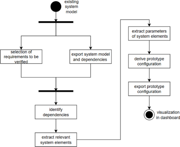
Development of the Process Chain Addressing this research gap, the article at hand presents a process chain for systematic extraction of test-relevant system elements and parameters from system models, enabling V&V engineers to set required prototype configurations. Through systematic literature analysis, related research is analyzed. Building on the analyzed literature, a process chain is developed based on an existing system model. System models in engineering complex technical systems serve as an appropriate starting point because a system is represented in a formalized and structured manner, capturing system elements, their interdependencies as well as relevant attributes. As a result, system models provide a traceable basis for linking verification activities to requirements considering affected system elements. Thus, systematically derivation of test-relevant parameters is realized. This makes the subsequent automation steps more transparent, consistent and reproducible. The process chain follows four overarching steps derived from literature: (1) selection of requirements to be verified, (2) automated identification of relevant system elements, (3) extraction of test-relevant parameters and (4) generation of prototype configurations. The prototype configuration is not predefined but derived from the identified elements and parameters. By representing engineering artifacts in SysML using a model-based approach and linking them according to the extended RFLP approach, cause effect chains can be utilized (Gräßler et al., 2022). The type of prototype is selected through the stage of the engineering process: function sample (A-sample), validation sample (B-sample), pre-series sample (C-sample) or series sample (D-sample). The starting point for the process chain is the system model, which contains the RFLP engineering artifacts. This serves as the manual trigger for applying the process chain. For illustration, the process chain is depicted in Figure 1 below as activity diagram in UML.
Figure 1: Prototype configuration process chain visualized as an activity diagram.
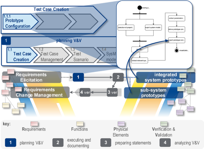
At the outset, the V&V engineer selects requirements with the encapsulated system properties utilizing the prototype to be configured. In parallel, system elements and relations of the system model are extracted. In the next activity, this dataset forms the basis for identifying dependencies – starting from the selected requirements or properties. Through end-to- end traceability within a system model, effect chains are identified and all additionally relevant system elements are identified. Using parameters of these relevant system elements, prototype configuration is derived. The prototype configuration contains all system elements subordinate to the physical element identified as relevant in the containment tree, including their specifying parameters. The configuration of the required prototype is then exported to be visualized as a prepared dashboard for the V&V engineer. The structure of the dashboard visualization is based on a standard procedure for dashboard design (cf. (Burch and Schmid, 2023)). The process chain for generating prototype configuration presented in this article is located in the first phase of the ToRRE method published in (Graessler and Ebel, 2025) (Figure 2). When planning and modeling test cases, it is necessary to define a suitable test item or prototype. This process chain is used for test case and test scenario planning to efficiently define a prototype required as the test item of a test case. V&V engineers are enabled to define prototype configurations to be executed in planned test cases. This implementation ensures a systematic approach within the overall planning, executing and analyzing V&V in engineering complex technical systems. It is classified in the V-model of VDI guideline 2206 (VDI/VDE2206:2021). Specifically, the method consists of four sequential
Utilizing System Models for Early Prototype Configurations 193 activities. First, V&V activities are planned. This involves deriving test cases from use cases and requirements as well as creating test scenarios (cf. (Graessler et al., 2025)). The created test cases and test scenarios, including the expected results, are modeled in the system model to enable traceability and consistent information flow (cf. (Gräßler and Ebel, 2025)). The second ToRRE phase involves executing planned test cases and test scenarios within tests and documenting test execution and test results. In addition to the documentation, test results are modeled as actual results within the same system model. The third ToRRE phase involves deriving statements from actual results as these are compared with expected results from test cases. Finally, these statements are used to analyze V&V activities carried out. Successful tests include those whose actual result matched the expected result. If expected results and actual results differ, model-based effect chains are used for impact analysis.
Figure 2: Process chain integrated in ToRRE.
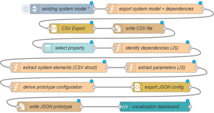
Technical Implementation To support practical application, the process chain developed is implemented as a Node-RED flow (Figure 3). From system models, system elements and their corresponding parameters are exported to CSV files and merged into a uniform template structure for prototype configuration.
The Node-RED flow implements the process chain to derive a prototype configuration from an existing SysML system model to be visualized in a dashboard. The technical architecture follows Node-RED’s typical message model, in which information is successively passed between individual
194 Graessler and Ebel processing nodes via the msg object and enriched step by step. The implemented process chain combines automated model initialization, data export, user-guided selection of system properties, dependency analysis, parameter extraction, configuration generation and dashboard-based visualization. The technical implementation of the process chain into the Node-RED flow is described as follows.
At the beginning implemented process chain, the existing system model, which is exported in a machine-readable data format csv, is imported by an initialization node from the corresponding file path. This node is automatically triggered when the flow starts. It generates a structured JSON message representing the loaded model information. This creates a reproducible starting point for further processing. Subsequently, a function node handles the preparation of the model export. In this step, the incoming model is extended with a set of exemplary dependencies. Technically, this is achieved by transforming the payload within the message, whereby both the model reference and the associated dependencies are stored in a common data structure. This structure forms the basis for a subsequent tabular export. The export is performed via a CSV conversion node, which converts the previously generated JSON structure into a line-based, comma-separated format. A simple serialization is used, in which the data is employed in a compact structure without additional header lines. A file output node then persists the resulting export artifact in the Node-RED runtime environment.
After the initial export, the interactive part of the implemented process chain begins. The user can select system requirements via a dashboard dropdown. This selection serves as a central parameterization point, as it determines the subsequent analysis path. The properties selected via the user interface are passed to downstream processing and additionally stored as a separate message property, ensuring it remains available in later processing steps. In this way, the context of the user’s decision is preserved across multiple nodes.
In the next processing step of the implemented process chain, system components dependent on the selected system properties are identified. The corresponding function node performs a model-based dependency resolution. Dependent elements are derived from the selected properties and stored as a structured list in the message. This list serves as input for the extraction of relevant system elements. In this process, each identified dependent element is converted into a uniform tabular intermediate structure. This normalization is technically significant because it makes subsequent processing independent of the original representation of the dependencies.
Parameter extraction is carried out subsequently. For each identified system element, the information and corresponding parameter are derived and stored together with the element in a new data structure. This results in a set of element-related parameter entries that serves as the technical basis for the subsequent prototype configuration. This procedure maps a typical transformation chain: Starting from system requirements, dependencies in form of effect chains are first identified, relevant elements are extracted and configuration-relevant parameters are generated.
Utilizing System Models for Early Prototype Configurations 195 The actual derivation of the prototype configuration takes place in a further function node. This node combines the previously selected requirements and the extracted parameters into a configuration object. The resulting object thus describes which system requirements were considered and which element- related parameters are relevant for the prototype. Technically, this prototype description is a separate message which allows to retain additional metadata while the prototype configuration is specifically addressed for output. A JSON node is used to persist the prototype configuration. This specifically serializes the generated configuration structure into a machine-readable representation. The formatted output facilitates both machine-based further processing and manual inspection. A downstream file node then writes the JSON representation persistently to the runtime environment. Here, too, storage is designed to be overwriting, so that an updated prototype configuration is generated.
Figure 3: Process chain implemented as Node-RED flow.
The integrated process chain is completed by a dashboard template that visualizes the successful completion of prototype configuration processing. The user interface is divided into two areas: a control area for selecting the system requirement and a visualization area for displaying the result status. The visualization itself is implemented as a static HTML component and indicates that the prototype data has been provided. Thus, the dashboard forms a simple human-machine interface through which both parameterization and result feedback take place. The dashboard is implemented as Node- RED dashboard. Using these results, the V&V engineer can now identify the relevant system elements and their associated parameters. An actual prototype can then be planned based on this prototype configuration.
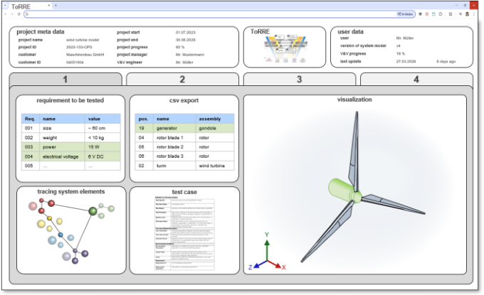
The developed and implemented process chain is carried out in accordance with the application evaluation of the Design Research Methodology. Two applications are used for this purpose: first, developing a drone simulation as part of the EU research project CREXDATA; and second, an academic wind turbine case study. In the CREXDATA project, a generic data platform is being developed that enables a workflow-based application of advanced artificial intelligence technologies, including in the disaster management of extreme weather events. The platform includes domain-specific simulation models such as the Gazebo robotics simulation. To configure the virtual prototype for verifying the “battery consumption” requirement, the process chain identifies the necessary system elements: battery, power, and payload. Using these system elements, a simplified robotics simulation can be implemented to examine static battery consumption while accounting for current wind conditions. In the case of the wind turbine, the goal is to test and verify the requirement regarding the wind turbine’s power output. By executing the process chain as a Node-RED flow, the networked system elements relevant to the requirement are first identified from the SysML system model. Relevant system elements are the generator, the nacelle, and the rotor, consisting of the rotor hub and rotor blades. To test the required power, the generator must be driven by the rotor. The results of the executed process chain are visualized for the V&V engineer in the dashboard (Figure 4) and enable a simple configuration of the prototype.
Figure 4: Dashboard visualization of wind turbine case.
Finally, processed data is visualized in a dashboard to clearly display and analyze configurations of suitable prototypes and parameters. Manual V&V effort is reduced by automating parts of the process chain developed. Furthermore, implementation of the process chain supports continuous
Utilizing System Models for Early Prototype Configurations 197 verification across different engineering stages and ensures efficient V&V for complex, interdisciplinary systems. Additionally, the process chain seeks to enhance traceability between RFLP elements and verification activities, thereby fostering a consistent application of MBSE principles in V&V processes.
DISCUSSION OF RESULTS AND CONCLUSION The implemented process chain in a Node-RED flow indicates that system models support systematic identification of test-relevant system elements and parameters in early engineering phases. With respect to RQ1, Node-RED flow demonstrates how an existing system model can be exported, enriched with dependency information and processed through a defined transformation chain. By selecting a specific system property to be tested and verified, related dependencies, system elements and associated parameters are derived in a reproducible manner. This shows that system models serve as a central information basis for early V&V activities, especially when dependencies between requirements, functions, physical elements and parameters are explicitly represented in the underlying system model. However, the quality of the identified test-relevant information strongly depends on the completeness, consistency and semantic richness of the system model. Regarding RQ2, the model-based derivation of prototype configurations can improve the efficiency of V&V planning as phase 1 of the ToRRE method when derivation process is standardized and automated. The flow illustrates that once a system property is selected, the relevant elements and parameters can be transformed into a structured prototype configuration without manual re-interpretation of the model. This can reduce effort in identifying test items, defining and preparing prototype scope and configuration. Efficiency gains are particularly likely when models are regularly maintained, dependencies are machine-readable and the generated configurations can be directly reused in simulation, testing or prototyping environments. In contrast, if the model is incomplete or requires extensive manual correction, benefits of automation are reduced and the flow risks fail. Implementing such a standardized model-based approach into existing MBSE process chains can positively affect traceability, time requirements and the quality of early prototyping (RQ3). The demonstrated Node-RED flow creates a continuous information path from the system model to the prototype configuration. This supports traceability because each generated prototype configuration can be related back to the original system property and its dependent elements. Time requirements are reduced through automated data transformation and consistent reuse of model information. Overall, the process chain developed suggests that standardized MBSE-implemented process chains make early V&V activities more transparent, repeatable and better aligned with the evolving system model. Limitations of the concept are that connection to the Cameo Systems Modeler REST API has not yet been implemented, meaning that the current workflow does not retrieve or synchronize model data directly from the original MBSE environment. In addition, the dashboard is currently limited due to missing image and 3d viewer visualization.
198 Graessler and Ebel Furthermore, the concept does not yet consider already existing prototype configurations of the system to be engineered or even previous engineering projects. As a result, the current approach cannot compare newly derived configurations with previous ones, detect redundancies or support iterative refinement based on existing prototype knowledge.
Nevertheless, the concept presented for systematic derivation of prototype configurations by utilizing system models and dependencies of system elements contributes to increased efficiency in early property assurance during engineering complex technical systems.
REFERENCES
Bender, B. and Gericke, K. (2021) Pahl/Beitz Engineering Design: Methods and Application of Successful Product Development, 9th edn., Berlin, Heidelberg. Blessing, L. T. and Chakrabarti, A. (2009) DRM, a Design Research Methodology,
London, Springer. Brings, J., Bohn, P., Bandyszak, T., Föcker, F. and Daun, M. (2016) ‘Model-Based Prototype Development to Support Early Validation of Cyber-Physical System Specifications’, REFSQ Workshops. Burch, M. and Schmid, M. (2023) Dashboard design, United States, River Publishers. Delligatti, L. (2014) SysML distilled: A brief guide to the systems modeling language,
Upper Saddle River, NJ, Addison-Wesley. Friedenthal, S., Moore, A. and Steiner, R. (2015) A practical guide to SysML: The systems modeling language, 3rd edn., Amsterdam, Waltham, Mass., Elsevier. Graessler, I. and Ebel, M. (2025) ‘Test-oriented Resilient Requirements Engineering
(ToRRE): Extending Model-based Effect Chain Analysis to Verification Objectives’, in Proceedings of the Design Society, Volume 5: ICED25, pp. 3031–3040. Graessler, I., Ebel, M. and Pottebaum, J. (2025) ‘Method for systematic generation of test scenarios for early customer involvement’, CIRP DESIGN: 35th CIRP Design Conference. Patras, Greece. Graessler, I. and Hentze, J. (2020) ‘The new V-Model of VDI 2206 and its validation’,
at - Automatisierungstechnik, vol. 68, no. 5, pp. 312–324. Gräßler, I. (2015) ‘Implementation-oriented synthesis of mechatronic reference models: Implementation-oriented synthesis of mechatronic reference models’, Konferenzband der VDI Mechatronik: Fachtagung Mechatronik 2015. Dortmund. Gräßler, I. and Ebel, M. (2025) ‘Holistic Metadata Model for Verification and
Validation in the Development of Complex Technical Systems’, 36. DfX Symposium 2025. Hamburg. Gräßler, I. and Oleff, C. (2022) Systems engineering: Verstehen und industriell umsetzen, Berlin, Heidelberg, Springer Vieweg. Gräßler, I., Roesmann, D., Hillebrand, S. and Pottebaum, J. (2022) ‘Information
Model for Hybrid Prototyping in Design Reviews of Assembly Stations’, Procedia CIRP. Gulf of Naples, Italy. Gräßler, I., Wiechel, D., Koch, A.-S., Preuß, D. and Oleff, C. (2022) ‘Model-based effect-chain analysis for complex systems’, Proceedings of the Design. Cavtat, Croatia, May 23.-26. Gräßler, I., Wiechel, D. and Oleff, C. (2022) ‘Extended RFLP for complex technical
systems’, Proceedings of 8th IEEE International Symposium on Systems Engineering 2022.
Utilizing System Models for Early Prototype Configurations 199 Li, Y., Wang, Y., Zheng, Y., Xu, C., Zhao, Y., Zhang, C. and Guo, L. (2025) ‘MBSE-
Based Digital Prototypes Development Approach for Gas Path System’, IEEE Access, vol. 13, pp. 209729–209741. Mahmood, I., Kausar, T., Sarjoughian, H. S., Malik, A. W. and Riaz, N. (2019) ‘An Integrated Modeling, Simulation and Analysis Framework for Engineering Complex Systems’ Object Management Group (2024) IBM Rational Unified Process for SE (RUP-SE). Object Management Group (2025) About the Unified Modeling Language
Specification. Pfeifer, T. (1996) ‘Phases of Quality Management’, in Eversheim, W. (ed.) Production and Management: “Betriebshütte”, Berlin, Springer. Pottebaum, J. and Gräßler, I. (2020) ‘Information Quality in Product Development:
Model-Based Systems Engineering with Explicit Consideration of Uncertainty’, Konstruktion, vol. 2020, 11–20, pp. 76–83. VDI/VDE (2021) 2206: VDI/VDE 2206 Development of mechatronic and cyberphysical systems, Düsseldorf: Beuth Verlag GmbH. Walden, D. D., Roedler, G. J., Forsberg, K., Hamelin, R. D. and Shortell, T. M. (eds)
(2015) Systems engineering handbook: A guide for system life cycle processes and activities, Hoboken, N.J. Weilkiens, T. (2014) Systems Engineering mit SysML/UML: Modellierung, Analyse, Design, 3rd edn., Heidelberg.
FIND THE COMPLETE VOLUME IN THE AHFE DIGITAL BOOKSTORE
Explore the complete digital volume
Human Systems Engineering and Design (IHSED2026): Future Trends and Applications
Read this individual research paper free through the original publisher, or explore the full digital proceedings book.