Jia Hao, Yuxuan Liu, Hongwei Niu, Xiaonan Yang, Yuhan Hu (2025). Adaptive Control Point Manipulation Technique for Free-Form Deformation Based on Gesture Interaction. In: Human-Computer Interaction & Emerging Technologies. AHFE Open Access, vol. 195, pp. 439–448. https://doi.org/10.54941/ahfe1006261
Currently, the majority of Computer-Aided Design (CAD) software adopts a feature-based parametric modeling approach, which effectively captures and represents the detailed attributes of design objects. Despite its precision and utility, this method demands extensive parameter adjustments within the constructed solid models to accommodate design modifications. Such complexity imposes significant constraints on the fluidity and flexibility required during the conceptual design phase, thereby impeding the expression of innovative design ideas. Furthermore, traditional CAD software predominantly relies on the "mouse and keyboard" interaction paradigm. This approach maps three-dimensional manipulation commands onto one-dimensional or two-dimensional input signals, which reduces the naturalness and intuitiveness of the modeling process. Consequently, there is a pressing need to develop advanced three-dimensional modeling methodologies that support free-form deformation (FFD) and integrate novel interaction paradigms to enhance user experience and foster design creativity. The concept of free-form deformation, first introduced by Sederberg and Parry (1986), involves embedding a geometric object into a control lattice defined by a set of control points. The deformation of the lattice, driven by manipulating these control points, is propagated to the embedded object, resulting in its transformation. Over time, free-form deformation technology has evolved significantly. A method for deforming geometric models was proposed to enhance usability by replacing grid-based operations with direct point manipulation. This approach was later refined with Dirichlet free-form deformation, which automates the generation of influence regions and calculates spatial density using constraint points. Subsequently, advancements introduced adaptive control point generation, multi-resolution editing, and hierarchical deformation, significantly improving the flexibility and precision of free-form deformation techniques. Parallel to advancements in FFD, gesture-based interaction has emerged as a novel interaction technology. Gesture interaction provides a more natural and intuitive mode of operation compared to traditional WIMP user interfaces by capturing hand movements and translating them into control commands. Prior research has demonstrated that gesture-based systems are not only easier for new users to adopt but also enable more immersive and efficient manipulation of virtual objects. However, challenges remain in bridging the gap between gesture-based input and precise control in modeling environments, particularly in the context of free-form deformation. This paper proposes a gesture-based adaptive control point manipulation technique for free-form deformation, which integrates gesture interaction into the free-form deformation process. In order to address the interaction amplitude mapping issue inherent in gesture interaction, a control point adaptive manipulation method based on mapping functions is designed, aiming at improving user interaction experience and enhancing model editing efficiency during the conceptual design phase. First, the study compares and analyzes the basis functions and deformation tools of free-form deformation to optimize the initial control point layout. Three mapping functions are developed to address the mapping discrepancies between hand gesture movement speed and control point movement speed during gesture interaction. To evaluate the interaction efficiency and operation smoothness of these three mapping modes, a comparative experiment is conducted involving 15 participants, which identifies the optimal mapping mode for interaction performance. Each of the participants needs to perform 3 rounds of control point movement operations in the experimental scenarios with 5 different movement distances preset by the system, under three different mapping modes, for a total of 45 operations. Metrics recorded include task completion time, operation accuracy and user preference. An adaptive control method for control points based on the optimal mapping function is designed, defining adaptive parameters within the mapping pattern and providing an adaptive parameter adjustment method for new users. Finally, an evaluation experiment is conducted with 10 participants to assess the effectiveness of the proposed adaptive control methods. Participants are required to perform specified model deformation tasks using both the "mouse and keyboard" interaction paradigm and the gesture-based interaction paradigm. Key metrics, including interaction accuracy and user preferences, are recorded for analysis. The results indicate that the gesture-based interaction paradigm not only achieves satisfactory interaction accuracy but also offers notable advantages in terms of enhanced immersion and reduced fatigue compared to the traditional "mouse and keyboard" interaction paradigm.
Computer-Aided Design (CAD) refers to a technology where designers use computer devices and associated software tools to create, modify, analyze, and optimize design solutions. The concept of CAD was first introduced in the early 1960s by researchers at MIT (Riesenfeld et al., 2015). The origins of CAD technology can be traced back to the 1950s when Patrick Hanratty developed the first numerical control system, “PRONTO” (Baltes, 2024). Over more than six decades of development, CAD technology has evolved from a simple graphical system focused on drawing and output functions to
a more intelligent, integrated, standardized, and networked system. Today, it has led to the creation of numerous commercial CAD software products, such as AutoCAD, SolidWorks, and PRO/E (Connolly, 1999). The application fields of CAD have also expanded from mechanical processing to areas such as artistic design, 3D printing, and virtual reality, reflecting a trend of diversified development.
Currently, most CAD systems for model construction utilize feature- based parametric modeling. This approach effectively captures the detailed attributes of design objects, making it more aligned with practical engineering applications. However, after the construction of the solid model, adjusting various complex parameters is required for modifications (Camba et al., 2016). This can be restrictive, especially in the early stages of product design, such as conceptual design, as feature modeling limits the expression of design thinking and impedes innovative design solutions. In contrast to feature-based modeling, spatial deformation, as an important tool in geometric modeling, can effectively simulate the deformation of flexible objects while maintaining the topological relationships of the deformed object. Free-Form Deformation (FFD) technology, proposed by Sederberg et al. (1986), is a typical example of spatial deformation techniques. This approach embeds the object model into a control volume formed by control points and deforms the model by moving these control points. Due to its generality, local deformability, and consistency, FFD technology has garnered widespread attention from researchers worldwide. When applied to CAD model editing, FFD offers certain advantages over feature-based parametric models in terms of ease of manipulation, while also being better suited for local and small-scale modifications and adjustments to model details.
In early CAD systems, users conveyed their design intent to the computer by writing on a two-dimensional coordinate system on a graphical interface with a light pen. As development progressed, the “mouse + keyboard” combination gradually became the mainstream mode of CAD interaction, now adopted by most CAD software. In recent years, with the ongoing advancements in human-computer interaction (HCI) research, new interaction modalities such as gesture interaction, voice interaction, touch interaction, and eye-tracking interaction have emerged and been widely applied in fields like intelligent driving, virtual reality (VR), augmented reality (AR), and healthcare education (Shi et al., 2024). In the context of increasingly emphasizing innovation in product design, the limitations of the “mouse + keyboard” control mode have also become more apparent. Firstly, as two-dimensional input devices, the keyboard and mouse require users to manually map three-dimensional commands in the cognitive process into one-dimensional and two-dimensional signals for input. This conversion can affect the naturalness of CAD model manipulation (Chu et al., 1997). Secondly, within the WIMP (Windows, Icon, Menu, Pointer) interface environment used by most CAD software, users must allocate significant attention to mapping mouse and keyboard commands and interpreting menu icons and functions that are not directly related to the design process. This can lead to unnecessary cognitive load for the user. Therefore, integrating new human-computer interaction modalities into the
Adaptive Control Point Manipulation Technique for Free-Form Deformation 441
CAD modeling process could reduce cognitive load during the concept design phase while enhancing manipulation convenience and naturalness. Based on such a research background, this paper focuses on the research of adaptive control technology for free-form control points based on gesture interaction, combining the construction of free-form models and deformation theory, integrating gesture interaction into the process of free-form deformation control, and aiming at the interaction amplitude mapping problem existing in the gesture interaction process, designing a control point adaptive control method based on mapping functions, to improve user interaction experience and enhance the model editing efficiency in the conceptual design phase.
RELATED WORKS Sederberg and Parry first proposed the concept of Free-Form Deformation (FFD) technology in 1986. The FFD technique assumes that objects are elastic and embeds them into a control volume composed of control points. It establishes a mapping relationship between the solid points within and on the surface of the object and the control points. By moving the control points, the control volume is deformed, and through the mapping relationship, this deformation is translated into the object’s deformation.
One of the important factors affecting the effect of FFD is the basis function. The basis function describes the mapping relationship between the coordinates of the solid points on the object in the deformation space and the coordinates of all control points contained in the control volume. It can be understood that the basis function defines the entire deformation space of FFD. When FFD was first proposed, Bernstein polynomials were used as the basis function (Sederberg et al., 1986). Due to the inherent characteristics of Bernstein polynomials, the movement of control points causes the deformation of all solids in the entire deformation space, thus achieving global deformation. Some researchers suggested using rational Bernstein polynomials as the basis function (Davis et al., 1991). Rational Bernstein polynomials add a weight degree of freedom on top of the existing three positional degrees of freedom of the control points. By adjusting the weights, the influence range and degree of the control points on the object’s deformation can be regulated, although the effect of the weight factor on the deformation is not intuitive. Greissmair and Purgathofer (1989) chose uniform B-spline basis functions as the FFD basis function, utilizing the piecewise nature of uniform B-splines to achieve local deformation. Lamousin and Waggenspack (1994) proposed FFD based on Non-Uniform Rational B- Splines (NURBS), which simultaneously have the local control characteristics of B-spline basis functions and the weight terms calculated based on rational formulas. Additionally, the distribution of control points is no longer limited to simple uniform arrangements and can be adjusted according to the desired level of detail for the deformation. McDonnell and Qin (2007) proposed FFD based on compactly supported radial basis functions (Ellipsoidal Radial Basis Functions, EBFs). This deformation method defines the deformation space as a linear combination of compactly supported radial basis functions.
The control grid vertices are parameterized into a local coordinate system constructed with the radial basis function center as the origin, and the influence range of the control points in the grid can be modified by setting the compact support radius parameter of the radial basis functions. Another key factor affecting the deformation effect in FFD is the user-controlled manipulator of FFD.
Another key factor affecting the deformation effect in FFD is the user- controlled manipulator of FFD, which can be classified into four types based on dimensional attributes: volume-based (3D), surface-based (2D), curve-based (1D), and point-based (0D). Volume-based FFD generates a closely spaced set of parallel hexahedra that envelop the object, with each vertex acting as a control point. Surface-based FFD was first proposed by Feng et al., which uses two parameterized surfaces as deformation tools to establish a mapping relationship between the object to be deformed and the two parameterized surfaces. During deformation, the shape of the parameterized surfaces is adjusted, and the deformation effect is automatically transferred to the object through the mapping. Surface-based FFD is relatively simple in editing the position of control points, thus showing significant improvements in interactivity and deformation functionality compared to volume-based FFD. Curve-based FFD was first proposed by Chang and Rockwood, which extends the de Casteljau algorithm to FFD and uses Bezier curves as deformation tools, controlling the object’s deformation through control points laid out on the curve. Curve-based FFD is suitable for bending deformations around an axis and has certain advantages in interactivity and usability. However, due to its relatively limited deformation capabilities, it is often used in practical applications for global deformation of objects. McDonnell proposed a point-based FFD (Point- Based Free-Form Deformation, PB-FFD) technique, which can adaptively generate a control point array around the object to be deformed and support direct manipulation of deformation, multi-resolution manipulation, and hierarchical reconstruction of the deformation space. Point-based FFD has higher degrees of freedom and stronger interactivity, showing significant application potential.
With the development of human-computer interaction technology, new interaction modalities such as voice interaction, gesture interaction, and eye movement interaction are constantly emerging. These new interaction modalities make the interaction behavior between users and devices more natural and smooth, bringing a new interactive experience to users. Gestures, as a common form of communication in human daily life, possess natural and intuitive interactive characteristics and clear expressive functions. In a broad sense, gestures include the physical movements of a person’s arms, head, body, etc. In a narrow sense, gestures specifically refer to hand postures and movements that include fingers and arms, which can be either with a single hand or with both hands working together. The subsequent content of this article mainly focuses on the narrow definition of gestures, that is, focusing on the identification and processing of hand features. Gesture interaction technology captures human hand movements through sensing devices, processes and analyzes them, and translates them into
Adaptive Control Point Manipulation Technique for Free-Form Deformation 443
operation commands to control devices. Research on gesture interaction in the field of human-computer interaction can be traced back to the 1980s. Gesture interaction can be used as an independent interaction modality or in conjunction with other interaction modalities. Buchmann et al. found through research that a gesture-based user interface has a more intuitive interaction experience compared to traditional WIMP-based user interfaces. For new users without experience, they can quickly get started without much additional training; Deller et al. proposed that in virtual reality and augmented reality environments, gesture interaction can provide users with a better sense of interaction immersion; Reiner et al. applied gesture interaction technology to the control process of media functions inside cars, using gestures to execute control commands, which greatly reduces the driver’s deviation of sight due to operating the dashboard buttons inside the vehicle.
CONTROL POINT ADAPTIVE MANIPULATION BASED ON MAPPING FUNCTION In human-computer interaction methods represented by gesture interaction, the mapping amplitude of the interaction process is a key factor affecting interaction efficiency. Interaction space mapping refers to the spatial correspondence between the operation space and the visual space. The range of space that users can operate is called the operation space, while the range of the interaction environment that can be visually perceived by users is called the visual space. Interaction space mapping converts instructions input by users through keyboards, mice, gestures, etc., into “visual space structure” information constructed in the computer, and maps this information into the position parameters of virtual controllers such as cursors in the virtual space through programs. Interaction space mapping mainly includes two parts: mapping mode and mapping scale. The interaction mapping mode refers to the response relationship between the motion mode of physical interaction devices and virtual tools. The interaction mapping scale refers to the proportional relationship between the physical interaction devices and virtual tools in terms of motion amplitude, which is commonly also known as the mapping ratio (Cursor-to-Display ratio, CD), defined as CD=L/L’, where L is the distance the interaction device moves in the operation space, and L’ is the distance the cursor moves on the screen. By microelementizing time, the ratio of moving distances can be converted into the ratio of moving speeds, thus CD is also a speed mapping equation. The mapping ratio CD affects the range and accuracy of gesture movements; a larger mapping ratio can achieve operation coverage of the visual space within a small operation space, while a smaller mapping ratio can achieve high-precision operations for the local range of the visual space. Therefore, if the mapping ratio design of the interaction system is unreasonable, it will directly lead to a decrease in the interaction performance of the system.
We have designed three gesture and control point movement speed mapping modes with distinct characteristics: linear mapping mode, segmented speed mapping mode, and “S” curve mapping mode. In the linear mapping mode, the gesture movement has a fixed mapping ratio
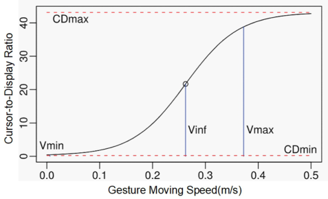
with the cursor movement speed on the screen; the segmented speed mapping mode references the dual-precision interaction technology from interactive mapping research, defining two mapping ratios for coarse and fine granularity. Through these two different interaction accuracies, it achieves rapid displacement and fine local manipulation, respectively; the “S” curve mapping mode (as shown in Figure 1) references a mapping mode proposed in a paper on gesture interaction in large display scenarios (Nancel, 2015). This mapping function can dynamically adjust the mapping ratio based on changes in gesture movement speed, and while partly inheriting the advantages of dual-precision interaction technology, it also smooths out the process of accuracy changes.
Figure 1: The “S” curve mapping mode.
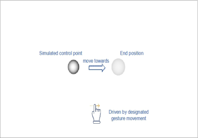
To explore the mapping modes between different gestures and control point movement speeds for gesture interaction control efficiency and user manipulation fluency, in order to select the mapping function relationship with the best interaction efficiency and fluency, we designed and conducted a comparative experiment on gesture and control point movement speed mapping modes. The experiment used Python as the code framework for the development of the experimental platform, adopted the Python toolkit supported by VTK (Visualization Toolkit) as the graphical display framework, and constructed a control point display window. For gesture signal recognition, the Leap Motion Controller was used as the gesture recognition device. A total of 15 individuals without gesture interaction experience were invited to participate in the experiment, including 10 males and 5 females, with an average age of 21 years among the subjects. During the experiment, participants were required to use designated gestures to perform translation operations on the simulated control point(a deep gray solid sphere) located on the left side of the interface (as shown in Figure 2). By making a hand gesture, the control point begins to move to the preset end position (a light-colored spherical net), and when the gesture is released, the control point stops moving, indicating the end of one operation.
Adaptive Control Point Manipulation Technique for Free-Form Deformation 445
Figure 2: Experiment interface.
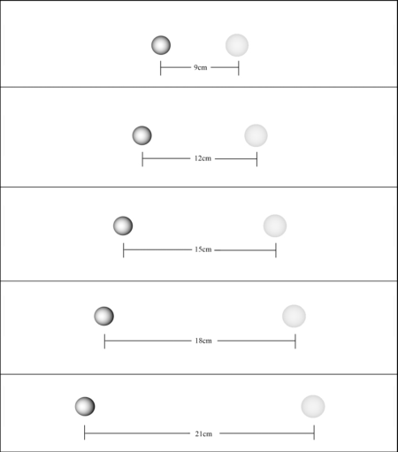
Each participant needs to perform 45 control point movement operations, executing 15 operations under each of the three different gesture-to- control point movement speed mapping modes, divided into 3 rounds. In each round, the system will present the experimental scenarios with 5 different movement distances in a random order to the participants (as shown in Figure 3). Participants need to move the control point to the destination according to the instructions given by the system through gestures and stop as required before proceeding to the next experiment.
Figure 3: Schematic diagram of 5 types of mobile distance experimental scenarios.
Each participant is required to perform 45 control point movement operations, executing 15 operations under each of three different gesture-to- control point movement speed mapping modes, divided into three rounds. In each round, the system will present five different movement distance scenarios (as shown in Figure 3) in a randomized order to the participant. The participant must move the control point to the destination according to the instructions given by the system and stop as required before proceeding to the next experiment. The experiment collects two data indicators for each movement operation: the time taken and the control accuracy. Additionally, a questionnaire is used to gather the participant’s subjective evaluations of the three mapping modes after completing the control experiments. Control accuracy is defined as Q = 1 −f/d, where d is the movement distance and f is the final movement error. The subjective evaluation indicators mainly include the ease of control point movement, control precision, and personal operation preference. Tables 1, 2, and 3 respectively show the statistical results of average time spent per movement, average control accuracy and participants’ scoring results.
Segmented Speed Mode Mapping Mode “S” Curve Mapping Mode The ease of movement 3.5 3.8 3.4 Control precision 2.4 3.6 3.8 Operation preference 3.1 3.4 3.5
Based on the data results, under the condition of equal control point movement distance, the average single movement operation time of the “S”
Adaptive Control Point Manipulation Technique for Free-Form Deformation 447
curve mapping function is smaller compared to the other two mapping modes, indicating that the continuous mapping ratio defined by the “S”curve mapping function has a positive effect on improving the efficiency of control point movement. In terms of average operation accuracy, the differences among the three mapping modes are not significant, with the “S” curve mapping function having a slight advantage. Furthermore, the “S” curve mapping function is considered to have higher controllability and precision by the experimental participants, leading to a higher preference level among them.
CONCLUSION
The feature-based parametric modeling approach provided by CAD technology struggles to support the generation of innovative design schemes during the conceptual design phase. This paper proposes a control point adaptive manipulation method based on gesture interaction, employing free-form deformation technology based on control points as a 3D model editing tool. Through gesture interaction, the manipulation of the control point deformation tool’s movement is controlled. To address the issue of the difficulty in matching the amplitude of gesture manipulation with the movement of model control points, three types of mapping functions between gestures and control point movement speeds have been designed and compared. This approach enhances the interaction efficiency of the free-form deformation process and improves the user’s interactive experience. In future research, we will explore more types of interaction mapping functions to further enhance the efficiency and smoothness of the user’s gesture interaction control process. Additionally, we will consider providing some preset gesture types for users to choose from based on their preferences, to accommodate individual user preferences.
REFERENCES
Baltes, C. (2024). Patrick J. Hanratty: Pioneer in commercial CAD/CAM software systems. IEEE Annals of the History of Computing, 46(4), 50–57. Borrel, P., & Bechmann, D. (1991). Deformation of n-dimensional objects. In
Proceedings of the first ACM symposium on Solid modeling foundations and CAD/CAM applications (pp. 351–369). Buchmann, V., Violich, S., Billinghurst, M., & Cockburn, A. (2004, June).
FingARtips: Gesture based direct manipulation in Augmented Reality. In Proceedings of the 2nd international conference on Computer graphics and interactive techniques in Australasia and South East Asia (pp. 212–221). Camba, J. D., Contero, M., & Company, P. (2016). Parametric CAD modeling: An analysis of strategies for design reusability. Computer-aided design, 74, 18–31. Chu, C. C. P., Dani, T. H., & Gadh, R. (1997). Multi-sensory user interface for
a virtual-reality-based computeraided design system. Computer-Aided Design, 29(10), 709–725. Connolly, P. E. (1999). CAD software industry trends and directions. The Engineering Design Graphics Journal, 63(1). Coquillart, S. (1990). Extended free-form deformation: A sculpturing tool for 3D
geometric modeling. In Proceedings of the 17th annual conference on Computer graphics and interactive techniques (pp. 187–196).
Davis, O. R. (1991). Free-form deformation as an interactive modeling tool.
J. Imaging Technology, 17(4), 181. Deller, M., Ebert, A., Bender, M., & Hagen, H. (2006). Flexible gesture recognition for immersive virtual environments. In Tenth International Conference on Information Visualisation (IV’06) (pp. 563–568). IEEE. Feng, J., Ma, L., & Peng, Q. (1996). A new free-form deformation through the
control of parametric surfaces. Computers & Graphics, 20(4), 531–539. Feng, J., Shao, J., Jin, X., Peng, Q., & Forrest, A. R. (2006). Multiresolution free-form deformation with subdivision surface of arbitrary topology. The Visual Computer, 22, 28–42. Gain, J., & Bechmann, D. (2008). A survey of spatial deformation from a user-
centered perspective. ACM Transactions on Graphics (TOG), 27(4), 1–21. Griessmair, J., & Purgathofer, W. (1989). Deformation of Solids with Trivariate B-Splines. In Eurographics (Vol. 89, pp. 137–148). Hsu, W. M., Hughes, J. F., & Kaufman, H. (1992). Direct manipulation of free-form
deformations. ACM Siggraph Computer Graphics, 26(2), 177–184. Kobayashi, K. G., & Ootsubo, K. (2003). t-FFD: Free-form deformation by using triangular mesh. In Proceedings of the eighth ACM symposium on Solid modeling and applications (pp. 226–234). Lamousin, H. J., & Waggenspack, N. N. (1994). NURBS-based free-form deformations. IEEE Computer Graphics and Applications, 14(6), 59–65. Lazarus F, Coquillart S, Jancène P. Axial deformations: An intuitive deformation
technique[J]. Computer-Aided Design, 1994, 26(8): 607–613. MacCracken, R., & Joy, K. I. (1996). Free-form deformations with lattices of arbitrary topology. In Proceedings of the 23rd annual conference on Computer graphics and interactive techniques (pp. 181–188). McDonnell, K. T., & Qin, H. (2007). PB-FFD: A point-based technique for free-form
deformation. Journal of Graphics Tools, 12(3), 25–41. Moccozet, L., & Thalmann, N. M. (1997). Dirichlet free-form deformations and their application to hand simulation (pp. 93–102). IEEE. Nancel, M., Pietriga, E., Chapuis, O., & Beaudouin-Lafon, M. (2015). Mid-air
pointing on ultra-walls. ACM Transactions on Computer-Human Interaction (TOCHI), 22(5), 1–62. Riesenfeld, R. F., Haimes, R., & Cohen, E. (2015). Initiating a CAD renaissance: Multidisciplinary analysis driven design: Framework for a new generation of advanced computational design, engineering and manufacturing environments. Computer Methods in Applied Mechanics and Engineering, 284, 1054–1072. Sederberg, T. W., & Parry, S. R. (1986). Free-form deformation of solid geometric
models. In Proceedings of the 13th annual conference on Computer graphics and interactive techniques (pp. 151–160). Shi, Y., Yi, X., Liang, C., Qin, Y., Wang, Y., Yan, Y.,... & Du, F. (2024). HCI research and innovation in China: A 10-year perspective. International Journal of Human– Computer Interaction, 40(8), 1799–1831. Singh, K., & Fiume, E. (1998). Wires: a geometric deformation technique. In
Proceedings of the 25th annual conference on Computer graphics and interactive techniques (pp. 405–414). Song, W., & Yang, X. (2005). Free-form deformation with weighted T-spline.
The Visual Computer, 21, 139–151. Yoon, S. H., & Kim, M. S. (2006). Sweep-based freeform deformations. In Computer Graphics Forum (Vol. 25, No. 3, pp. 487–496). Oxford, UK and Boston, USA: Blackwell Publishing, Inc.
Read this individual research paper free through the original publisher, or explore the full digital proceedings book.
ISBN 978-1-964867-71-7
Explore this ISBN in the AHFE Bookstore ↗Listed in the July 2026 bookstore catalogue; search by ISBN to confirm current availability · Digital book purchase optional