Rahul Sharma (2025). Aspects of Nano Scale SAP of 18-8 Stainless Steel with Permanent Rare Earth Magnetic Tool for Humans. In: Human Aspects of Advanced Manufacturing, Production Management and Process Control. AHFE Open Access, vol. 184, pp. 91–101. https://doi.org/10.54941/ahfe1006453
Serious health issues can develop in people from eating contaminated food, especially if the food production pipelines are not adequately maintained. Preventing biofilm formation on the interior surfaces of pipelines in these industries is crucial for ensuring food safety. SAP is an advanced, non-traditional technique used for achieving nano scale finishing on very hard non-ferrous materials like stainless steel and ceramics. For precise finishes, costly abrasives such as Alumina, Silicon carbide, and Diamond powder are utilised. Although SAP is not a novel concept, it requires initial setup restoration, high operational costs, and have few thermal issues with abrasive materials. This study explores the parameters of nano scale finishing using sintered abrasives like Green Silicon Carbide and Electrolytic Iron powder with permanent rare earth magnets arranged in a zig-zag pattern on 18-8 Stainless Steel. The findings indicate that the gap between the 18-8 stainless steel work-piece and SAP magnetic tool has the greatest impact on PISF, followed by circumferential speed, achieving highest of 94% PISF with a 1.17% material extraction rate.
Many severe diseases like Botulism, Cholera, Listeriosis, and Hepatitis A etc. flourish in human being due to the consumption of contaminated food or juices (Awuchi, 2023). Root cause of contamination of these food products is from the origin means the Agro-Industries where these are being manufactured. While manufacturing, the raw material of the food products needs to be mixed and processed. For these purposes, the food material mixtures are transmitted from one machine to another through very lengthy Stainless-steel pipes lines. These pipe lines have micro scale surface roughness on the inner walls due to which the fluid particles get stuck on the walls with time. Processing environment for these mixtures is essential to prevent spoilage. But due to these gathered micro layers of rotten food particles, it originates the Fungai and other harmful bacteria. Hence the fluid material passing through the pipe line will also get contaminated. This results to the reduction of shelf life of food and agro products and also causes many major health issues when consumed by the human beings. So, avoiding the biofilm formation on the inner walls of pipe line is essential.
Due to the non-corrosive, light in weight, less prone to the environment conditions, good strength and durability properties, SUS 304L is the most commonly used material for the fabrication of these pipe lines (Sharma & Pradhan, 2020). But the internal surface finishing of these pipe lines is still a challenge. There are many traditional methods to increase the internal surface nano finish of pipes. But these methods require a complex set up which is not feasible for every shape and size of stainless-steel pipes (Jain, 2009). Nano scale surface finishing using sintered abrasive particles is a non-traditional technique. This technique is very effective specially on non-ferrous metals like 18–8 stainless steel and ceramics.
Abrasive powder finishing is a method which utilizes a carefully regulated force of permanent magnets or electro magnets to manipulate sintered or non-sintered ferromagnetic abrasive particles with iron particles (Jain, 2009). These particles are often blended with fine abrasives like Al2O3, SiC, CBN, or diamond. The sintered mixture is referred as ferromagnetic or magnetic abrasive particles (Singh, 2005). Consequently, the tool used in this process is exceptionally durable. This approach circumvents many issues found in traditional superfinishing techniques that employ rigid grinding wheels, which can introduce micro-cracks, geometric inaccuracies, and surface distortions. The magnetic field functions as a binder, holding ferromagnetic abrasive particles in place within the machining gap. The magnetic abrasive particles form a magnetic abrasive brush that is usually 1–3 mm thick due to dipole-dipole interactions between the magnetic poles along the magnetic force lines (Jayswal, Jain, and Dixit, 2005). In the case of un-sintered magnetic and abrasive particles mixed as a powder, the abrasive particles become entangled within the chains formed by the ferromagnetic particles. Magnetic abrasive finishing is an advanced finishing method employed to achieve high-quality surface finishes on a variety of components (Kim, 2003). This technique is effective for treating surfaces of different shapes and materials, such as flat plates, shafts, bearing components, screws, tubes, and other mechanical parts requiring superior surface quality. Recent technological advancements have led to the widespread use of stainless steel in electronic, biochemical, and medical instrumentation due to its anti- oxidizing, anti-corrosive properties, and attractive surface finish (Lin, Yang and Chow, 2007). For these applications, it is crucial that stainless steel components have an exceptionally smooth surface to avoid contamination. Ideally, the finish should be so refined that it resembles a mirror. However, stainless steel, being both tough and challenging to work with, presents difficulties in achieving a high-quality finish using traditional methods, especially for thin-plate materials. Shinmura et al. (1984) investigated how various factors such as vibration frequency, magnetic flux density, amplitude, finishing time, and working gap influence the finishing characteristics when using sintered magnetic abrasives for nano finishing. Their research revealed that the efficiency of the finishing process was primarily influenced by vibration and magnetic flux density.
Yamaguchi and Shinmura (2004) examined the application of magnetic abrasive powder finishing for polishing the interior surfaces of alumina ceramic tubes using diamond-ceramic magnetic abrasives. Their study focused on how variations in abrasive particle size and lubricant volume
Aspects of Nano Scale SAP of 18–8 Stainless Steel 93
influenced the precision inner surface finishing process. Shinmura et al. (1987) conducted experiments using abrasives with varying sizes of iron and abrasive particles. Their results demonstrated that the size of the iron particles had a greater impact on performance than the size of the abrasive particles. In a related study, Shinmura et al. (1994) found that increasing the circumferential speed led to a higher material extraction rate. Additionally, Shinmura and Aizawa (1989) observed that finishing efficiency improved with higher tool speeds when applied to ceramic materials for enhanced surface quality. Yamaguchi et al. (2005) investigated the use of aluminum oxide composite magnetic abrasives with an average diameter of 80µm for finishing SUS304 stainless steel bent tubes. This composite, consisting of Al2O3 with grit sizes less than 10µm, was sintered with iron powder under controlled high pressure and temperature. Mori et al. (2003) examined the process mechanisms using sintered magnetic abrasive particles. Wang and Hu (2005) focused on the inner surface finishing of tubing material 316L stainless steel, Ly12 aluminum alloy, and H62 brass concluding that brass had the highest material extraction rate among the selected three. Khangura et al. (2010) and Yamaguchi and Shinmura (1999) reviewed current technologies for manufacturing magnetic abrasives and noted that sintered magnetic abrasives generally provide the best surface finish across various work materials. The present research focus on the nano scale surface finishing of 18–8 stainless steel using rotational motion of the sintered abrasive particles with permanent rare earth magnetic tool.
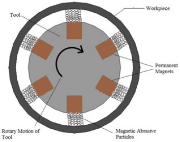
PROCESS PRINCIPLE The Sintered Abrasive Polishing (SAP) tool, equipped with rare earth permanent magnets, is positioned inside the 18–8 stainless steel tube to generate a magnetic field that attracts and directs the sintered magnetic abrasives to the finishing area. As the SAP tool rotates within the 18–8 stainless steel tube, the particles of sintered magnetic abrasive powder, influenced by the force of rare earth magnetic field, also moves along the inner surface of the thin tube. Hence, it removes a micro scale layer of material from it.
Figure 1: Principal of SAP.
94 Sharma
Total six circular rare earth permanent magnets are installed in a disc of thickness 25mm by punching six holes arranged in a zig-zag pattern around the circular axis with two different diameters (three permanent magnets per circle). The magnets are secured in these holes using strong epoxy resin. The design takes into account both the working gap and the size of the sintered abrasive particles as well. Sintered magnetic abrasive particles, driven by magnetic flux, are used to finish the workpiece. For this micro scale surface finishing, Green Silicon Carbide-based sintered abrasives are utilized as the magnetic abrasives.
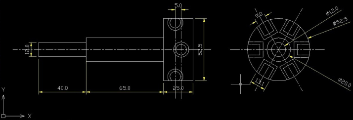
DESIGN AND FABRICATION OF SAP MAGNETIC TOOL AND WORKPIECES A specialized setup has been created for experimentation with minimal errors. The design phase is completed using SolidWorks software. Since the focus is on the surface finish of stainless steel using rare permanent magnets, Mild Steel, known for its excellent mechanical strength, is chosen for tool fabrication. The mild steel rod is machined into the required dimensions (as per design) of Spindle Shaft of length 40 mm and diameter 12 mm. The shaft of the bottom part Rotor is fabricated up to the length of 65 mm and diameter 20 mm. Similarly, the Rotor is prepared with the length of 25 mm and 52.5 mm diameter as shown in Figure 2. Additionally, six holes are drilled in the rotor at two different diameters, with three holes in each circle positioned 120
apart and 60
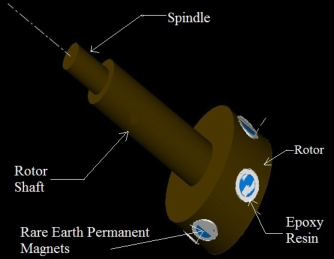
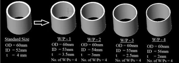
from the circle’s center. Figure 3 shows the design and fabricated SAP tool. Next, rare-earth magnets are embedded and secured with strong epoxy resin. As for the workpieces, the thickness- to-internal diameter ratio (t/di) must be less than 0.077 for thin cylinders or tubes So, a standard size 18–8 stainless steel pipe is modified to the necessary dimensions shown in Figure 4.
Figure 2: Dimensional details of SAP magnetic tool.
Aspects of Nano Scale SAP of 18–8 Stainless Steel 95
Figure 3: 3-D design model and actual fabricated SAP magnetic tool.Figure 4: Dimensional details of 18–8 stainless steel workpieces.
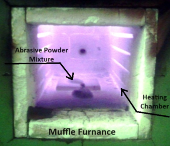
SINTERING OF MAGNETIC ABRASIVES In this work, magnetic abrasives were created using a muffle furnace sintering technique. The abrasives were prepared from a powder mixture of electrolytic iron (Grit Size 100) and green silicon carbide powder (Grit Size 200), sintered at 1100
C. The percentage of weight is taken as 70% and 30% respectably shown in Figure 5.
Figure 5: Sintering of abrasive in muffle furnace and magnetic separation test.
96 Sharma
The resulting solid mass was ground, then sifted through a sieve shaker to obtain powders of various grit sizes. A magnetic separation test was conducted to evaluate the bonding strength. Approximately 10 grams of the abrasive was spread on a non-magnetic flat surface, and a permanent magnet was moved across it. Abrasives with strong bonding were then collected and used in the experiments.
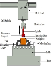
EXPERIMENTAL PROCEDURE AND TEST CONDITIONS The SAP magnetic tool is attached to the drill machine’s holding jaw, while the workpiece is secured in a pipe vice on the X-Y-Z table. Figure 6 has machine vertical drill machine set up for polishing. SAP magnetic tool and drill spindle are driven by a motor via belt-pulley system in a vertical drill machine. To minimize interference with the magnetic field, all components, except for the magnets, are made from non-magnetic materials.
Figure 6: SAP machine set-up.
Abrasive is applied to the SAP tool and attracted to the magnetic poles, forming few tiny brushes. As the SAP magnetic tool rotates at a lower speed, the abrasives move in a circular motion, effectively removing surface material. The details of all parameters have been included in Table 1.
Table 1: SAP magnetic polishing conditions.
Table available in the original PDF paper.
Criteria Delineation Work Piece material and Dimensions 18–8 Stainless Steel of total length of 70 mm Standard available outer Diameter of pipe is 60 mm And Inner Diameter ranges from 53 mm to 56 mm Abrasive Green Silicon Carbide (30%) sintered with Electrolytic Iron
Powder (70%) Type of Lubricant Diesel Oil IS1448 (P:32) Amount of
5% of weight of abrasive
Lubrication Magnets Six in Zig-Zag pattern with Internal angle 60
&
120
towards center of two different axial circles Continued
Aspects of Nano Scale SAP of 18–8 Stainless Steel 97
Table 1: Continued Criteria Delineation
Table available in the original PDF paper.
Running Speed 600 to 1300 rotations per minute SA Particle Size Grit No 75 of 200 microns to Grit No 180 of 76 microns Amount of Abrasive 2 gm to 8 gm per experimental run Experiment time 20 min to 50 min per run Magnetic Flux
0.17 Tesla to 0.45 Tesla
Density
Each parameter is assessed across four levels, resulting in a matrix with 5 factors, each at 4 levels. The rotational speed range was determined through experimental analysis of the drill machine’s speed. To achieve optimal surface finish, research was conducted comparing permanent magnets to electromagnets, focusing on magnetic field intensity relative to distance. Subsequently, the type and shape of magnets were selected along with their respective levels. Experiments on permanent rare earth magnets were conducted to establish an effective working gap range. Table 2 presents the various parameters and their values used in the experiments. For calculating the Performance Index Surface Finish as PISF and Material Extraction Rate that is MER, surface roughness values and the weight of each workpiece were measured before and after the experiments.
Table 2: Process parameters and levels.
Table available in the original PDF paper.
Range of Process Parameters Level 1 to Level 4 Rotational Speed (rpm) 650 to 1280 Workpiece-Tool Gap (mm) 0.5 to 3.5 SA Particle Size (microns/Grit No) 75 to 180 Amount of Abrasive powder per experiment (gm) 2 to 8 Run Time per experiment (Minutes) 20 to 50 Measured Magnetic Flux Density (Tesla) 0.17 to 0.38
RESULTS AND DISCUSSION
A full factorial design would necessitate 1024 experiments (44). Instead, the statistical Genichi Taguchi approach is employed, utilizing an L16 (4ˆ5) orthogonal array to reduce the number of experiment runs and streamline the experimental process. Table 3 outlines the combinations of parameters and their levels as designed. With 5 factors and 4 levels each, the L16 (4ˆ5) array comprises 16 runs. During the experiments, parameters such as magnet arrangement, workpiece materials, and abrasives were kept constant. Key variables including the quantity of magnetic abrasives, workpiece rotational speed, magnetic flux density, and machining duration were altered to examine their impact on PISF. MER and PISF associated with the factors are also listed in Table 3. To examine how the working gap affects PISF, it was adjusted within the range of 0.5 mm to 3.5 mm. Since the magnetic field flux density of the permanent rare earth magnet is proportional to this distance,
98 Sharma
it varied from 0.17 T to 0.38 T. Other parameters included the amount of abrasives, ranging from 2g to 8g, circumferential speed, which ranged from 650 rpm to 1280 rpm, and machining time, spanning from 20 minutes to 50 minutes.
Table 3: Orthogonal array of parameters and obtained results.
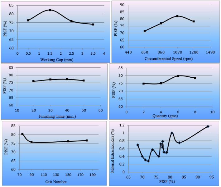
Figure 7: Variation of PISF & MER with input parameters.
Aspects of Nano Scale SAP of 18–8 Stainless Steel 99
The results, depicted in Figure 7, indicate that initially increasing the actual working gap between the 18–8 stainless steel pipe workpiece and the SA rotary magnetic tool enhances surface finish due to the effective formation of the magnetic abrasive brush. However, once the gap exceeds 1.5 mm, magnetic flux density declines, leading to a reduction in PISF. This decrease in flux density weakens the magnetic abrasive brush’s contact area and strength (Geeng-Wei Chang, Biing-Hwa, and Yan, Rong- Tzong Hsu, 2002). Higher flux density initially improves the finishing force. During testing, workpiece rotational speed varied from 650 to 1280 rpm, with magnetic abrasive amounts ranging from 2 g to 8 g and 5% lubricant. Machining times ranged from 20 to 50 minutes, abrasive particle sizes varied from grit 75 to grit 180, and working gaps ranged from 0.5 mm to 3.5 mm. PISF increased with rotational speed up to 1070 rpm but decreased at higher speeds due to centrifugal forces ejecting abrasive grains. Longer machining times initially improved PISF, but beyond 40 minutes, the effect diminished as abrasive particles lost their sharpness and density due to material accumulation (Gursharan Sing Gandhi, 2013). Increasing abrasive quantity initially improved PISF, but beyond 6g, excess abrasive powder began to fall off. PISF decreased with larger abrasive particles but increased again with finer particles (grit 90 to 180).
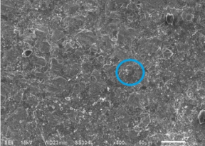
Figure 8: SEM analysis of surface finish.
Therefore, larger abrasive particles remove more material, but for a smoother finish, smaller particles are preferable. This study compares PISF with material extraction rates, showing that finer finishes on 18–8 stainless steel require greater material removal, revealing that uniform surface layers and fine finishes are achieved by removing more material shown in Figure 8.
CONCLUSION
1. The nano scale SAP using magnetic tool technique was used in this study to enhance the surface quality of 18–8 stainless steel. It was observed that the variations in operational parameters influence the workpiece surface quality. 2. The gap between the workpiece and magnetic tool was identified as the most crucial parameter, followed by circumferential speed. Additionally, machining time, sintered abrasive quantity, and SA particle size had a lesser impact on surface finish improvements.
100 Sharma
3. The effective gap between the 18–8 stainless steel cylindrical workpiece and rare earth magnetic tool notably affects both surface roughness and material extraction. The data show that material extraction rate increases more rapidly with a decreasing actual working gap (between the cylindrical workpieces and rotary magnetic tool) compared to the change in surface roughness values. 4. SEM analysis declare the nano scale improvement in surface finish of hard metal 18-8 stainless steel using SAP magnetic tool.
REFERENCES
Awuchi, C. G. (2023). HACCP, quality, and food safety management in food and agricultural systems. Cogent Food & Agriculture, 9(1). Geeng-Wei Chang, Biing-Hwa, and Yan, Rong-Tzong Hsu (2002) “Study on
cylindrical magnetic abrasive finishing using unbounded magnetic abrasives” in International Journal of Tools & Manufacture, Volume 42. Gursharan Sing Gandhi (2013). “Internal finishing of thick cylinders SUS304 tubes using Magnetic Abrasive Finishing Setup” in International Journal of Mechanical Science and civil Engineering, Volume 2. Kim J-D. (2003) “Polishing of ultra-clean inner surfaces using magnetic force”
in International Journal of Advanced Manufacturing Technology Volume 21, pp. 91–97. Lin, C-T., Yang, L-D. and Chow, H-M. (2007) “Study of magnetic abrasive finishing in free-form surface operations using the Taguchi method” in International Journal of Advance Manufacturing Technology, Volume 34, pp. 122–130. Mori, T., Hirota, K., and Kawashima, Y. (2003) “Clarification of Magnetic
Abrasive Finishing Mechanism” in Journal of Materials Possessing Technology, pp. 143–144. S. C. Jayswal, V. K. Jain, and P. M. Dixit (2005), “Modeling and simulation of magnetic abrasive finishing process” in International Journal of Advanced Manufacturing Technology, Volume 26, pp. 477–490. Sharma, Dr & Pradhan, Swastik. (2020) “Investigation of machinability criteria
during micro-abrasive finishing of SUS-304L steel using fuzzy combined with WASPAS approach” in Journal of the Brazilian Society of Mechanical Sciences and Engineering Volume 42, article number 116. Shinmura T., Takazawa K., Hatano E. and Aizawa T. (1984) “Study on Magnetic Abrasive Process” in Japan Society of Prec. Engg. Volume 18, No. 4 pp. 347–348. Shinmura T., Wang F. and Aizawa T. (1994), “Study on a New Finishing Process of
Fine Ceramics by Magnetic Abrasive Machining” in Japan Society of Prec. Engg., Volume 28, No. 2, pp. 99–104. Shinmura, T. and Aizawa, T. (1989) “Study on Internal Finishing of Non- Ferromagnetic Tubing by Magnetic Abrasive Machining Process”, Bulletin of Japan Society of Precision Engg, vol. 23(1), pp. 37–41. Shinmura, T., Takazawa, K. and Hatano, E. (1987) “Study on magnetic abrasive finishing-effects of various types of magnetic abrasives on finishing characteristics” in Bull Japan Society of Precision Engg., Volume. 21, No. 2, pp. 139–141. Singh L., Singh S. and Mishra P. S. (2010) “Performance of abrasives used in
magnetically assisted finishing: A state of the art review” in International Journal Abrasive Tech., Volume 3, pp. 215–227.
Aspects of Nano Scale SAP of 18–8 Stainless Steel 101
Singh, D. K., (2005) Investigations into Magnetic Abrasive Finishing of Plane Surfaces in Ph. D. Thesis. Indian Institute of Technology, Kanpur, India. V. K. Jain (2009) “Introduction to Micro-machining. Narosa Publishers” V. K. Jain, (2009) “Magnetic Field Assisted Abrasive Based Micro-/Nano-Finishing”
in Journal of Material Processing Technology, Volume 209, pp. 6022–6038. Wang Y. and Hu D. (2005) “Study on Inner Surface Finishing of Tubing by Magnetic Abrasive Finishing” in International Journal of Machine Tools and Manufacture, Volume 45, pp. 43–49, Shanghai Jiaotong University, Shanghai, China. Yamaguchi H. and Shinmura, T. (2004) “Internal finishing process for alumina
ceramic components by a magnetic field assisted finishing process” in Precision Engg., Volume. 28, pp. 135–142. Yamaguchi H., Shinmura, T. and Sekine M. (2005) “Uniform Internal Finishing of SUS304 Stainless Steel Bent Tube.” Yamaguchi, H. and Shinmura, T. (1999) “Study of the Surface Modification
Resulting from an Internal Magnetic Abrasive Finishing Process” in Wear, pp. 225–229: 246–255.
LISTED IN THE AHFE DIGITAL BOOKSTORE CATALOGUE
Explore the complete digital volume
Human Aspects of Advanced Manufacturing, Production Management and Process Control
Read this individual research paper free through the original publisher, or explore the full digital proceedings book.
ISBN 978-1-964867-60-1
Explore this ISBN in the AHFE Bookstore ↗Listed in the July 2026 bookstore catalogue; search by ISBN to confirm current availability · Digital book purchase optional