Minh Trinh, David Kötter, Ariane Chu, Mohamed Behery, Gerhard Lakemeyer, Oliver Petrovic, Christian Brecher (2023). Safe and Flexible Collaborative Assembly Processes Using Behavior Trees and Computer Vision. In: Intelligent Human Systems Integration (IHSI 2023): Integrating People and Intelligent Systems. AHFE Open Access, vol. 69, pp. 869–879. https://doi.org/10.54941/ahfe1002912
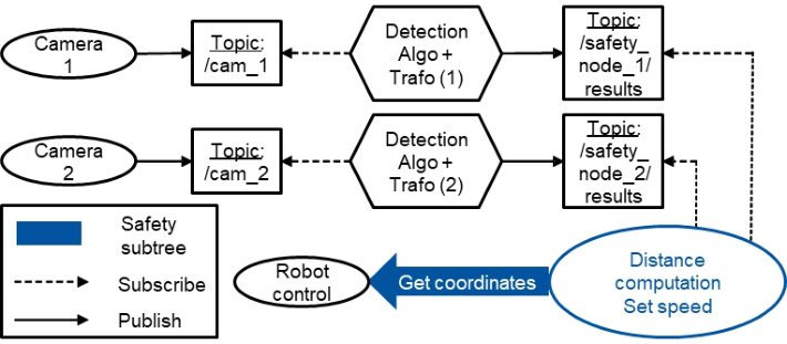
Human-robot-collaboration combines the strengths of humans, such as flexibility and dexterity, as well as the precision and efficiency of the cobot. However, small and medium-sized businesses (SMBs) often lack the expertise to plan and execute e.g. collaborative assembly processes, which still highly depend on manual work. This paper introduces a framework using behavior trees (BTs) and computer vision (CV) to simplify this process while complying with safety standards. In this way, SMBs are able to benefit from automation and become more resilient to global competition. BTs organize the behavior of a system in a tree structure [1], [2]. They are modular since nodes can be easily added or removed. Condition nodes check if a certain condition holds before an action node is executed, which leads to the reactivity of the trees. Finally, BTs are intuitive and human-understandable and can therefore be used by non-experts [3]. In preliminary works, BTs have been implemented for planning and execution of a collaborative assembly process [4]. Furthermore, an extension for an efficient task sharing and communication between human and cobots was developed in [5] using the Human Action Nodes (H-nodes). The H-node is crucial for BTs to handle collaborative tasks and reducing idle times. This node requires the use of CV for the cobot to recognize, whether the human has finished her sub-task and continue with the next one. In order to do so, the algorithm must be able to detect different assembly states and map them to the corresponding tree nodes. A further use of CV is the detection of assembly parts such as screws. This enables the cobot to autonomously recognize and handle specific components. Collaboration is the highest level of interaction between humans and cobots [4] due to a shared workspace and task. Therefore, it requires strict safety standards that are determined in the DIN EN ISO 10218 and DIN ISO/TS 15066 [6], [7], which e.g. regulate speed limits for cobots. The internal safety functions of cobots have been successfully extended with sensors, cameras, and CV algorithms [8]–[10] to avoid collisions with the human. The latter approach uses the object detection library OpenCV [11], for instance. OpenCV offers a hand detection algorithm, which is pretrained with more than 30.000 images of hands. In addition, it allows for a high frame rate, which is essential for real-time safety.In this paper, CV is used to enhance the CoboTrees (cobots and BTs) demonstrator within the Cluster of Excellence ’Internet of Production’ [12]. The demonstrator consists of a six degree-of-freedom Doosan M1013 cobot, which is controlled by the Robot Operating System (ROS) and two Intel RealSense D435 depth cameras. The BTs are modeled using the PyTrees library [13]. Using OpenCV, an object and assembly state detection algorithm is implemented e.g. for use in the H-nodes. Since the majority of accidents between robots and humans occur due to clamping or crushing of the human hand [14], a hand detector is implemented. It is evaluated regarding its compliance with existing safety standards. The resulting safety subtree integration in ROS is shown in Fig. 1.
INTRODUCTION AND BACKGROUND Human-robot collaboration (HRC) is gaining popularity in many industrial domains such as manufacturing and assembly. HRC processes are usually safety critical due to the close interaction between cobots and humans. How- ever, programming cobots for such tasks requires trial and error and a lot of fine tuning. Behavior trees (BTs) were introduced to robot programming offering flexibility and modularity which helps in code reuse.
BTs organize the behavior of a system in a tree structure consisting of nodes that are propagated by ticks (Iovino et al., 2022; Colledanchise and Ögren, 2018). BTs are modular since nodes or subtrees can be easily added or removed. Condition nodes check if a certain condition holds before an action node is executed, which leads to the reactivity of the trees. Nodes can be executed in sequence or parallel and return RUNNING, SUCCESS or FAILURE depending on their state. Selector nodes tick their subsequent nodes (children) until one returns RUNNING or SUCCESS. Finally, decora- tors are user-defined nodes. BTs are intuitive and human-understandable and can therefore be used by non-experts (Olsson et al., 2016).
In earlier works, BTs have been introduced for planning and execution of a collaborative assembly process (Baier et al., 2022). Furthermore, an exten- sion for an efficient task sharing and communication between human and cobots was proposed in (Behery et al., 2021) using the Human Action Nodes (H-nodes). The H-node is crucial for BTs to handle collaborative tasks and reducing idle times. This node requires the use of computer vision (CV) for the cobot to recognize, whether the human has finished her sub-task and continue with the next one. In order to do so, the algorithm must be able to detect different assembly states and map them to the corresponding tree nodes. A further use of CV is the detection of assembly parts such as screws. This enables the cobot to recognize and handle specific components.
Collaboration is the highest level of interaction between humans and cobots (Baier et al., 2022) due to a shared workspace and task. Therefore, it requires strict safety standards that are determined in the DIN EN ISO 10218 (DIN, 2012) and DIN ISO/TS 15066 (ISO, 2017). The latter defi- nes safety function such as speed and separation monitoring (SSM), which specifies a minimum protective distance between human and cobot and the- refore preventing collisions. The internal safety functions of cobots have been successfully extended with sensors, cameras, and CV algorithms (Scimmi et al., 2021; Kumar et al., 2019; Xu et al., 2015) to avoid collisions with the human. The latter approach uses the object detection library OpenCV (Bradski, 2000), for instance. OpenCV offers a hand detection algorithm, which is pretrained with more than 30.000 images of hands. In addition, it allows for a high frame rate, which is essential for real-time safety. Paxton et al. introduced CoSTAR a system and graphical user interface using BTs and vision for collaborative robots (Paxton et al., 2016). We further improve this concept by focusing on safety for collaborative processes.
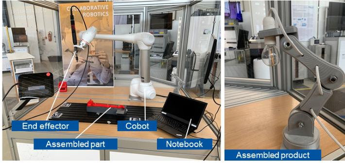
In this paper, CV is used to enhance the CoboTrees (cobots and BTs) demonstrator within the Cluster of Excellence ‘Internet of Production’ (Pen- nekamp et al., 2019). The demonstrator consists of a six degree-of-freedom Doosan M1013 cobot, which is controlled by the ROS Operating System (ROS) running on a notebook with CPU and two Intel RealSense D435 depth cameras. The BTs are modelled using the py_trees library1. Since most acci- dents between robots and humans occur due to clamping or crushing of the human hand (Haddadin, 2014), the OpenCV hand detector and SSM are implemented in a safety subtree. This method is evaluated regarding its com- pliance with existing safety standards and using an example assembly case. The CoboTrees demonstrator as well as the lamp to be assembled are shown Figure 1.
DESIGN, IMPLEMENTATION AND INTEGRATION This section describes the design, implementation, and integration of the CV- based SSM system in ROS using a BT for an assembly process. This system is designed in order to comply with the DIN ISO/TS 15066.
1https://github.com/splintered-reality/py_trees
Safe and Flexible Planning of Collaborative Assembly Processes Using Behavior Trees 871
Figure 1: CoboTrees demonstrator (left) and final product (right).Figure 2: System design of the ROS setup.
Design Overview of the Speed and Separation Monitoring System
Figure 2 shows the system design of the ROS setup with two integrated Intel RealSense cameras that publish RGB images under the respective topics. A subsequent detection algorithm and transformation module subscribes to the respective camera topic. The module uses the OpenCV hand detection algo- rithm to detect a human hand and the coordinates of its middle key point. This algorithm is pretrained with mediapipe hand images (Lugaresi et al., 2019). Since the coordinates of the hand are defined in the camera coor- dinate system, a transformation from the camera coordinate system to the robot coordinate system follows. The module publishes the coordinates of the hand. The distance computation module subscribes to the latter topic and computes the shortest distance from the middle key point of the hand to the cobot. Depending on the distance, the speed of the cobot is controlled. Three different modes for the speed are implemented: full speed, slow speed, and stop (zero velocity). In addition, a blackboard is used, which holds variables and values relevant to the cobot.
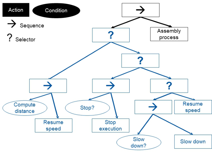
Figure 3: Behavior tree of an assembly process with an integrated safety subtree (in blue).
A safety subtree must be designed and integrated to the main BT, which designs the respective task. The BT for the assembly of the lamp in Figure 1 is shown in (Baier et al., 2022). With every tick the safety subtree checks if a hand is close to the cobot. Furthermore, it checks if a hand is in the environment before the cobot starts moving. Figure 3 shows the assembly BT with the safety subtree.
In Figure 3, using a selector node ensures, that its children are ticked from left to right, until one of them returns success. The distance computation module always returns failure to ensure, the speed of the cobot is set to the correct value afterwards. The condition nodes return running (which is turned into failure) unless one of the conditions is true. If one of the condi- tions is true, the respective action is carried out. The condition node returns success and the safety subtree itself returns success. Furthermore, the stop- ping module is further left than the one for slowing down. This underlines that stopping the cobot is more important than slowing down, which is itself more important than setting the speed to normal level.
Camera Integration
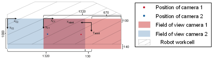
Figure 4 shows the positions of the two cameras and their field of view in relation to the coordinate system of the robot. The cameras are installed in parallel to the cobot’s workspace to detect hand in two-dimensional space. They are installed 1250 mm above the ground of the cobot’s workspace. The- refore, both cameras have a recording range of 1320 mm in the direction of the x-coordinate and 1000 mm in y-direction. They are arranged in a way that
Safe and Flexible Planning of Collaborative Assembly Processes Using Behavior Trees 873
Figure 4: Position of the cameras, the cobot and their coordinate systems.
ensures a view throughout the whole length of the workspace and to maxi- mize coverage. This is necessary, because depending on the cobot and hand position, the cobot may block the hand out of the camera’s view. The recor- ding area of the cameras starts 140 mm in front the work cell of the cobot. The image from camera 1 as well as the image from camera 2 are converted from an RGB image into a BGR image, since OpenCV follows BGR order, whereas the Intel RealSense camera outputs the image as an RGB image. For this task, the CvBridge2 is used.
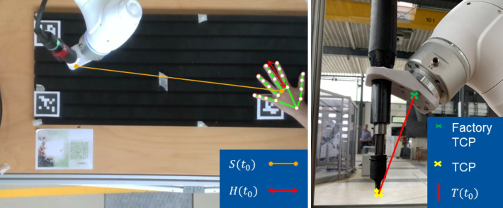
Detection Algorithm and Transformation The purpose of the detection algorithm and transformation module is to find the hand in the image provided by the camera, determine the middle key point of the hand and transform the coordinates of that point from the camera coordinate system into the robot coordinate system. If the detection algori- thm does not find a hand in the image, it publishes 999 for the x and 999 for the y-coordinate of the hand middle point. In this way, the computed dista- nce between the cobot and the middle point of the hand is big enough for any possible position of the cobot to not stop or slow down the cobot. If the OpenCV hand detection algorithm detects a hand in the provided image, the location of the 21 key points of the hand are determined. There is a trade- off between accuracy and computation speed. To reduce the computational cost, we only use the hand’s middle key point to calculate the distance betw- een the hand (middle point) and the cobot. The missing distance of the hand is considered as a constant added value (taken from a male experimentee, denoted H (t0) in Figure 5). If the algorithm finds a hand in the image, a computation is performed to transform the output of the detection algorithm from the camera coordinate system into the robot coordinate system with the length scale of millimeters. The transformation from pixels into millimeters in x-direction is done by multiplying the output from the middle hand key point with the maximum viewing distance of the camera in x-direction divided by the number of pixels in x-direction.
DISTANCE COMPUTATION With every tick of the BT, the distance computation module computes the distance between the hand and the cobot. Therefore, it uses an access function
2http://wiki.ros.org/cv_bridge
Figure 5: Visualization of H(t0) and T(t0).
to get the coordinates of the cobot position. Furthermore, it gets the coordina- tes of the hand middle point. If camera 2 does not detect a hand, the distance computation module computes the shortest distance between the cobot and the coordinates of the hand detected by camera 1. If camera 1 does not detect a hand, the action distance computation computes the shortest distance betw- een the hand middle key point and the cobot with the estimated hand middle key point position from camera 2. If both cameras detect hands, the distance is set according to the minimum computed value. Afterwards, the computed distance is written to the blackboard to check if the cobot can move with full, slow, or zero speed. The distance computation node always returns FAILURE, to ensure the selector node ticks its other children.
Speed Control There are six different parameters in the designed and implemented safety algorithms:
dist_stop: If the distance between the middle key point of the hand and the robot is smaller than dist_stop [m], the robot stops its movement.
dist_slow: If the distance between the middle key point of the hand and the robot is smaller than dist_slow [m] but bigger than dist_stop, the robot slows down.
set_speed: Set the speed to set_speed [m/s] if no hands are detected or the distance between the robot and the hand middle key point is larger than dist_stop.
Slow_speed: The parameter slow_speed can be changed to any real num- ber between zero and one. If the distance between the middle key point of the hand and the robot is smaller than dist_slow but bigger than dist_stop, the robot moves with slow_speed ∗set_speed.
To ensure the condition nodes return either SUCCESS or FAILURE, a deco- rator node is used prior to each condition node. In this way, none of the condition nodes returns RUNNING and the BT does not block. There are three different possibilities for the computed distance. First, if the computed distance is smaller than dist_stop, the robot is stopped and the node returns
Safe and Flexible Planning of Collaborative Assembly Processes Using Behavior Trees 875
Figure 6: Safety distance and its components according to (ISO, 2017).
SUCCESS. Therefore, the sequence node stops ticking its children. Second, if the computed distance is smaller than dist_slow, but bigger than dist_stop, the first condition node returns FAILURE since its condition is not met. The second condition is true and therefore, the speed is set to slow speed. More- over, the second condition node returns SUCCESS. Therefore, the sequence node returns SUCCESS as well and the cobot continues with slow speed. And thirdly, if the computed distance is bigger than dist_slow, the first and the second conditions are not met. Therefore, both condition nodes return FAILURE. The third condition is true and returns SUCCESS. Therefore, the cobot resumes at full speed.
Compliance With DIN ISO/TS 15066
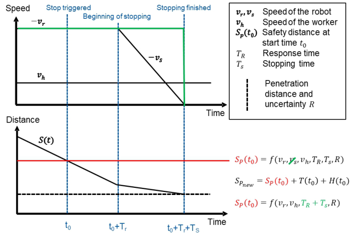
Figure 6 shows a graphical representation and calculation of the safety distance SP(t0) at time t0 and its components according to (ISO, 2017). To determine the response and stopping time TR and TS the cobot needs to move with 33 %, 66 % and 100 % of the total payload, whereas the maximum value of the measurements must be used. vr is the directed speed of the cobot towards the worker and vs the speed of the cobot from getting the stopping signal to the actual stop. The original equation for SP(t0) does not consider the length of the tool from the end of the cobot to the TCP. Furthermore, the CV algorithm returns the central point of the hand, which means another value for the distance from the central point of the hand to the biggest extend of the hand must be added as well. SP,new shows the modified equation. Here, T (t0) is the distance from the TCP to the biggest extend of the tool and H (t0) is the distance of the biggest extend from the middle of the hand to the end of the hand as shown in Figure 5.
To ensure the workers integrity in any situation, an optimization for the worst case is conducted, leading to the assumption that vs (t) = vr (t) and T = Ts + Tr, which is the time the system needs to detect a hand in the workspace of the cobot, to send the stopping signal and to stop the cobot. The variable T is determined as follows: the dist_stop variable is set to 990, which means as soon as a hand is detected by one or both cameras, the SSM system sends a stop signal and stops the cobot. To measure the exact time between moving the hand into the recording area and the stop of the cobot, the hand is held as close as possible to the recording area. The cobot must be loaded with 33 %, 66 % and 100 % of the maximum payload while determining Ts and Tr (T respectively). For each payload, 24 measurements are conducted with different positions of the cobot. In each of the 24 measurements, the hand is moved eight times in the recording area of camera one, eight times in the viewing area of camera two and eight times in the recording area of both cameras. As a result, T does not exceed 1.1 s. Therefore, T is set to 1.1 s.
Furthermore, the maximum speed of the cobot can be set to 1 m/s. The- refore, vr is set to 1 m/s. A measurement of the distance between the factory TCP and the TCP shows, T_max is 148 mm.
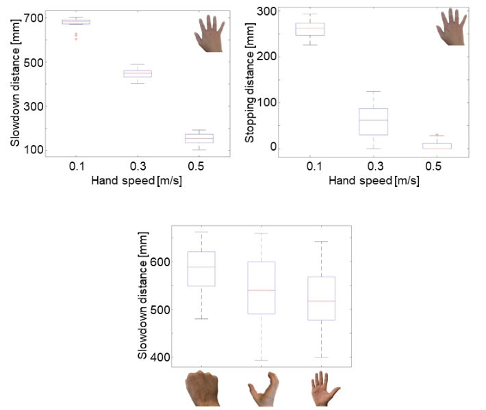
EVALUATION To evaluate the implemented algorithms, a hand moves with different speeds and gestures into the work cell of the cobot. A high-speed camera records the movement of the hand in front of a measuring tape. Afterwards, the recording is rewatched to determine the distance in which the cobot stops/slows down as accurately as possible. The hand speed is monitored with a smartwatch. Throughout the experiments, a deviation up to 10% from the defined hand speed is allowed. Furthermore, the cobot moves only in z-direction to simplify the distance measurement. The results should therefore be re-evaluated in the future for more complex movements. Four different hand gestures are evaluated (see Figure 7): flat hand (slow/stop), fist (slow), grab (slow) and upside-down (slow).
The experiments with a flat hand are conducted with three different hand speeds (0.1 m/s, 0.3 m/s, 0.5 m/s). Other gestures are evaluated with a speed of 0.1 m/s. For each gesture and speed, 24 tries are conducted. Throughout the experiment, dist_slow is set to 800 mm. The experiments with a flat hand are also evaluated for the stop of the cobot (dist_stop = 400mm). Further- more, the same gestures are evaluated with a working glove. In all attempts, the shortest distance between the cobot and the closest point of the hand to the cobot is measured.
The distance between the closest point of the hand to the cobot is measured and represented in boxplot diagrams. Figure 7 top left shows the results for the slowing down distance with different speeds and a flat hand. The exact hand gesture is shown in the corner on the upper right side. Figure 7 top right shows the results of the distance in which the cobot stops. The results for both evaluations are measured in the same experiment. First, the cobot slows down and afterwards, the cobot stops if the distance falls below 400 mm (dist_stop). With a hand speed of 0.3 m/s, the stop fails two times. With a
Safe and Flexible Planning of Collaborative Assembly Processes Using Behavior Trees 877
Figure 7: Distance for slowdown or stopping of cobot depending on hand gesture.
hand speed of 0.5 m/s, the stop fails 13/24 times. Figure 7 bottom shows the boxplot diagram of the distance in which the cobot slows down with different hand gestures. The algorithm was not able to detect a hand wearing working gloves, therefore, these results are omitted. In 13/24 tries for each gesture, the algorithm fails to detect a hand.
Depending on the parameters dist_stop and dist_slow, a reliable system for different hand speed can be obtained. The question is, if the value of the parameters is small enough to allow real collaboration between the human being and the cobot. Most CV algorithms are designed to run on a server GPU and not on a CPU from a laptop. The slow frame rate of 10 fps leads to a high value for dist_stop to satisfy the DIN ISO 15066. Therefore, no real collaboration between the robot and the worker is possible. For the use case of collaborative assembly of a lamp, the stopping distance is set to zero and the slowing distance is set to 0.6 m. This way, even if the worker moves fast towards the cobot, it slows down at least 10 mm before the worker hits the cobot. When the hand of the worker moves away from the light stand to grab the next screw to be fastened, the cobot accelerates to full speed.
CONCLUSION AND OUTLOOK In this paper an SSM system was developed to decrease hand related accidents during human-robot-collaboration. As control architecture, a BT is chosen
due to its modularity and reactivity. The system is designed in a generic way to ensure an easy integration of other body parts, detection algorithms and/or cameras at a later stage. Two Intel RealSense cameras are added to the exi- sting robot environment to track the hand position. For the hand detection, an algorithm from OpenCV pretrained with mediapipe hand images is used. The model for hand detection is embedded into an existing BT/ROS framew- ork. A safety subtree is implemented using py_trees. The distance is computed between the middle hand key point and the factory TCP of cobot. The mis- sing distances for the fingers and the tool are added as constants to the safety distances. Furthermore, this research conducted a quick way to get a conse- rvative estimation of the stopping distance to meet the guidelines from the European Union.
The designed algorithms can support an existing safety strategy. The use case shows that the designed SSM system improves the safety of a human during HRC. However, due to the use of a CPU only high values for the stop- ping distance are achieved that do not allow for real collaboration. Therefore, a GPU will be used in the future. Furthermore, experiments will be condu- cted for 3-dimensional detection of the whole human body. In addition, other cameras and CV algorithms can be tested and evaluated. The distance com- putation node will be extended to cover the whole cobot, not only its end effector. The CV module will be extended for detection of the assembly pro- duct as well as assembly states, used by the H-nodes for efficient task sharing and communication between human and cobot.
ACKNOWLEDGMENT
Funded by the Deutsche Forschungsgemeinschaft (DFG, German Research Foundation) under Germany’s Excellence Strategy – EXC-2023 Internet of Production – 390621612.
REFERENCES
Baier, R. et al. (2022) ‘A Framework for the Classification of Human-Robot Interactions Within the Internet of Production’, in Kurosu, M. (ed) Human-Computer Interaction. Technological Innovation, Cham, Springer International Publishing, pp. 427–454. Behery, M., Trinh, M. and Lakemeyer, G. (2021) ‘Human Action Nodes for Beha-
vior Trees’, Proceedings of the workshop Robotics for People – Perspectives on Interaction, Learning and Safety. Bradski, G. (2000) ‘The OpenCV Library’, Dr. Dobb’s Journal of Software Tools. Colledanchise, M. and Ögren, P. (2018) Behavior Trees in Robotics and AI, CRC Press. DIN (2012): DIN EN ISO 10218–1:2011 Industrieroboter – Sicherheitsanforderun-
gen, Teil 1: Roboter (ISO 10218–1:2011). Haddadin, S. (2014) Towards Safe Robots: Approaching Asimov’s 1st Law, Berlin, Heidelberg, Springer. Iovino, M., Scukins, E., Styrud, J., Ögren, P. and Smith, C. (2022) ‘A survey of Beh-
avior Trees in robotics and AI’, Robotics and Autonomous Systems, vol. 154, p. 104096.
Safe and Flexible Planning of Collaborative Assembly Processes Using Behavior Trees 879
ISO (2017): ISO/TS 15066:2016–02. Robots and robotic devices - Collaborative robots. Kumar, S., Arora, S. and Sahin, F. (2019) Speed and Separation Monitoring using
on-robot Time--of--Flight laser--ranging sensor arrays. Lugaresi, C. et al. (2019) MediaPipe: A Framework for Building Perception Pipelines [Online]. Available at http://arxiv.org/pdf/1906.08172v1. Paxton, C., Hundt, A., Jonathan, F., Guerin, K. and Hager, G. D. (2016) CoSTAR:
Instructing Collaborative Robots with Behavior Trees and Vision. Pennekamp, J. et al. (2019) ‘Towards an Infrastructure Enabling the Internet of Production’, 2019 IEEE International Conference on Industrial Cyber Physical Systems (ICPS). Taipei, Taiwan, 06.05.2019 - 09.05.2019, IEEE, pp. 31–37. Scimmi, L. S., Melchiorre, M., Troise, M., Mauro, S. and Pastorelli, S. (2021) ‘A
Practical and Effective Layout for a Safe Human-Robot Collaborative Assembly Task’, Applied Sciences, vol. 11, no. 4, p. 1763. Xu, D., Wu, X., Chen, Y.-L. and Xu, Y. (2015) ‘Online Dynamic Gesture Recognition for Human Robot Interaction’, Journal of Intelligent & Robotic Systems, vol. 77, 3–4, pp. 583–596.
LISTED IN THE AHFE DIGITAL BOOKSTORE CATALOGUE
Explore the complete digital volume
Intelligent Human Systems Integration (IHSI 2023): Integrating People and Intelligent Systems
Read this individual research paper free through the original publisher, or explore the full digital proceedings book.
ISBN 978-1-958651-45-2
Explore this ISBN in the AHFE Bookstore ↗Listed in the July 2026 bookstore catalogue; search by ISBN to confirm current availability · Digital book purchase optional