Fabian Arnold, Slim Krückemeier, Reiner Anderl (2022). Development of an Information Model for the Pre-process of Additive Manufacturing. In: Additive Manufacturing, Modeling Systems and 3D Prototyping. AHFE Open Access, vol. 34, pp. 62–68. https://doi.org/10.54941/ahfe1001590
Additive manufacturing has a variety of benefits that make it an exciting alternative to conventional manufacturing processes. For example, it is possible to manufacture customized, small volume parts with complex geometry in a short time to market. This ensures a steadily growing spread of additive manufacturing beyond its use in prototyping. However, it is difficult for additive manufacturing to compete with conventional manufacturing processes in terms of cost with growing batch sizes.The additive manufacturing process has to be optimized to improve economic efficiency while maintaining or increasing part quality. One approach is focusing on the pre-process. The AM pre-process comprises the determination of part orientation, the setting of manufacturing parameters, and the toolpath generation. Since all decisions made during this process step affect the subsequent manufacturing process, there is a lot of optimization potential.This paper develops an information model of the AM pre-process to map all information and its complex interdependencies. Therefore, a process model is developed and used to determine all input and output information describing the process steps and their relation to other process steps. It is tested for validation by performing the AM pre-process steps with a demonstrator part, ensuring all relevant information can be represented in the information model.
Additive manufacturing (AM) is an emerging manufacturing technology that developed from prototyping to the production of end-use parts, especially in recent years. This manufacturing technology reveals its potential when the opportunities for designing free-form surfaces, lattice structures, cavities or under-cuts are consistently utilized (Marquardt 2020). According to a study presented in Sculpteo (2021), AM users’ top benefits are the realization of complex geometries, quicker iteration in product design, mass customiza- tion, and lead-time reduction. Therefore, it is only adopted in industry sectors benefitting from these advantages (Marquardt 2020; Sculpteo 2021; Attaran 2017). For wider dissemination in the market, it is necessary to reduce the costs of additively manufactured parts through further optimization of the process technology as well as upstream and downstream processes while at the same time ensuring or increasing part quality. So, topics such as repeata- bility, reliability, process time, design assistance, or simulation tools have to be focused on in future research (Belkadi et al. 2018; Bonnard et al. 2010; Kim et al. 2015; Kim et al. 2017; Krückemeier et al. 2021; Marquardt 2020).
The digital twin concept is a promising approach for a holistic digitali- zation of the entire AM process chain. A digital twin is defined as a virtual
Development of an Information Model for the Pre-process of Additive Manufacturing 63
representation of a physical product, process or service (Stark et al. 2020). By utilizing data from all lifecycle phases, the digital twin can represent and predict machine states, perform optimizations or test new parameters in the virtual world before deploying them to the physical machine. The basis for all these applications is the digital representation of the AM process chain, which has to be broken down to an information model in the end. This paper provides a building block for a digital twin for additive manufacturing by developing an information model for the pre-process of additive manufactu- ring. The scope of the pre-process, comprising the process steps of nesting, generating support structure, slicing and machine data generation, has been selected due to its strong influence on the entire AM process. Understan- ding and representing the complex interrelationships within the pre-process and the downstream process steps offers great potential for digital twin for additive manufacturing.
RELATED WORK
The current digital thread used in additive manufacturing, based on STL files, has multiple shortcomings that hinder the development of advanced AM pro- cesses. Examples are the lack of technological information on the process and manufacturing condition such as surface finish, which does not allow CAD and AM system integration, or the fact that the STL format is only used in AM, which makes multi-process manufacturing impossible (Bonnard et al. 2019; Mies et al. 2016). To address these problems, developing a new digital thread is necessary. AM process modeling can help develop a comprehensive understanding of the workflows and is, therefore, the subject of current rese- arch. Feng et al. (2017) developed a multi-level hierarchical process model in SADT notation to improve interoperability between different manufactu- rers of LPBF systems. The top hierarchical level consists of the six activities “Model Product”; “Tesselate Product Model”; “Plan Process”, “LPBF Pro- cess”, “Post Process” and “Quality Inspection”. Lu et al. (2016) developed an information model in the form of a UML class diagram, which is intended to cover the information needs of different stakeholders, from the designer to the quality assurance personnel. As a basis for their information model, they use an SADT process model in which information is captured in a structu- red and organized manner. In the information model, information is divided into the categories product, process and resources. Belkadi et al. (2018) use BPMN as a modeling language to break down the workflows of the indi- vidual processes and the resources and information involved in them. They identified three main types of processes: Core processes, which contribute to the development of a product, support processes that are required by the core processes and control processes, which are necessary for planning and controlling the other processes.
METHODOLOGY
The first step in developing the information model consists of literature rese- arch in which individual process steps in the pre-process are identified, and
the information objects involved are determined. The results of this litera- ture research are collected and organized in a process model. The process model maps the structure of the additive manufacturing process chain by breaking down the processes into sub-processes. Subsequently, inputs and outputs are assigned to the individual subprocesses, representing informa- tion objects in the information model. The Structured Analysis and Design Technique (SADT) is used for this procedure. Due to its hierarchical structure and the ICOM notation, it allows splitting the process chain into any num- ber of subprocesses, and distinguishing between different types of data. In the second modeling step, the actual information model is created. It comprises both the information objects involved in the pre-process of additive manufa- cturing and fundamental functions. Therefore, an object-oriented modeling approach in the form of a UML class diagram is used. This allows repre- senting the properties of information objects in the form of attributes and their functionalities through operations. In a final validation, the information model presented in this paper is examined for suitability. For this purpose, the pre-process is run through using a demonstrator part, and the information model is filled with specific data.
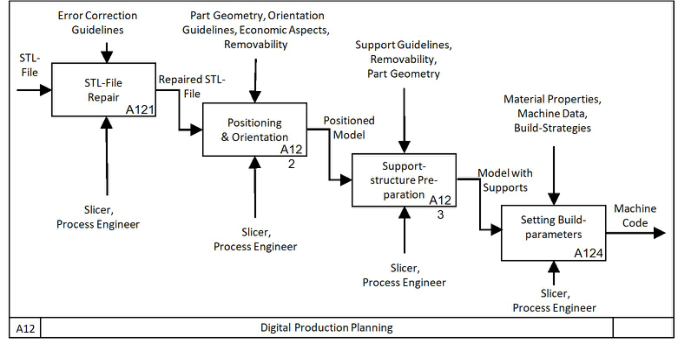
PROCESS MODEL In the process model, which the information model is based on, all sub- processes of additive manufacturing, starting with the product idea and ending with the post-processing of the printed part, are mapped. How- ever, this paper focuses exclusively on digital production planning in the pre-processing software. The process steps contained therein are shown in Figure 1. Digital production planning can be divided into four sub-processes, all of which are executed by a process engineer in the pre-processing software. The first step consists of repairing the STL file, which is the starting point for digital production planning. In this process, errors that occurred during the generation of the STL file, such as overlapping or missing polygons, which can cause problems during manufacturing, are repaired. The repaired model is then placed on the virtual build platform and orientated based on seve- ral influencing factors, such as part geometry or economic aspects. Once the optimal part orientation has been found, support structures are generated that support the component or anchor it to the build platform depending on the manufacturing process. Here, in addition to the removability of the sup- port structures, the part geometry also has a vital impact. Once the support structures have been created, the manufacturing parameters are selected in the final sub-process. These are influenced by the material properties, the machine data and the manufacturing strategy used and are decisive for the machine code exported from the pre-processing software.
INFORMATION MODEL In order to develop the information model in a structured manner, it is split up into a total of four interconnected submodels. These include product develo- pment, digital process planning, resources and process parameters. As far as
Development of an Information Model for the Pre-process of Additive Manufacturing 65
Figure 1: SADT-Diagram digital production planning.
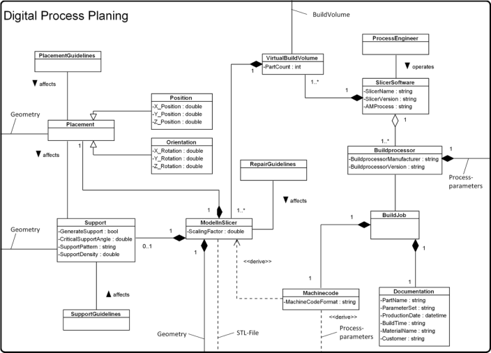
possible, the model was developed to be generally valid for all AM processes. In the case of process-specific information objects such as process parame- ters, the model represents the FLM and LPBF processes as examples, whereby the modular structure also allows later expansion to include other manufa- cturing processes. The first submodel depicts the product development, in which the CAD_Model of the part forms the central element. The CAD model is influenced by the List Of Requirements, Design For AM Guidelines, and Simulation methods such as FEM, CFD or MBS. To completely utilize the potential presented by the design freedom that accompanies AM technology, Topology Optimization can be used. Each CAD model has a Geometry that is represented in a separate class. Since it is difficult to describe complex geometries in detail in a UML class diagram, only the most important pro- perties such as the maximum dimensions and the volume and the surface area are represented by attributes in this class. Once the part’s design has been completed in the CAD software, the model is exported as a surface model, which is usually a STL-File. It is derived from the CAD model using Export Parameters. After importing the part model into the Slicer Software (Model In Slicer), it represents the central element for the digital process plan- ning, which can be seen in Figure 2. It has the same geometry as the STL-File, but can be scaled up or down according to need. All process steps in the slicer, from repairing the STL file to exporting the machine code, are performed by a Process Engineer. The first step in the slicer is to perform a repair of the STL file. Errors that may exist in the STL file are eliminated depending on the type of error to enable smooth production. Subsequently, the repaired model is arranged in the Virtual Build Volume of the slicer (Placement). The virtual build space is a subclass of the real Build Volume in the AM machine and has the same dimensions as the real build volume. The placement of a part can be split up into Position and Orientation in the three spatial dimensions. The placement is primarily influenced by the part’s Geometry and the Pla- cement Guidelines and usually represents a compromise between different optimization criteria such as build time or surface quality. After the model
Figure 2: Digital process planning submodel.
has been placed in the build space, the next step is generating Support structu- res. Support structures are generally required on all overhang surfaces whose angle relative to the build platform exceeds the critical overhang angle. The support pattern and the support density depend on the manufacturing pro- cess used and the particular application. The choice of support pattern and its contact points with the part are based on the part Geometry, Placement and Support Guidelines, which take aspects like the removability in the post pro- cess into account. Once all parts have been provided with the necessary Sup- ports, Process Parameters are selected. They are determined by the Material and the AM_Machine used. Based on the Process Parameter, the Build Broces- sor generates the Machine Code which is used to control the manufacturing machine. Together with further Documentation, the Machine Code forms a so-called Build Job, which contains all information about a single production cycle. The submodel resources includes the properties of the AM_Machine and the Material used in the printing process. Since these are process-specific parameters, both classes are subdivided for the LPBF and FLM processes. Regardless of the manufacturing process, all materials have a Melting Tempe- rature, a Chemical Composition and Mechanical Properties. Process-specific attributes include, in the case of LPBF material, properties like grain size, particle size distribution and flowability. For FLM, filament properties like diameter or color are described. The material used in the printing process influences both the CAD_Model and the choice of Process Parameters.
The second main class in the resources submodel represents the AM_Machine. Regardless of the manufacturing process, every additive
Development of an Information Model for the Pre-process of Additive Manufacturing 67
manufacturing system has at least one Build Volume whose dimensions determine the maximum part size that can be manufactured. The Mach- ine Data subclass defines, among other things, the minimum and maximum layer thicknesses that can be printed. The remaining machine data relevant for the pre-process are mapped in process-specific subclasses. In the case of the LPBF process these are laser and coater properties, and in the FLM process, the maximum extrusion and print bed temperature or the nozzle diameter. These properties define the limits within which the process para- meters can be selected. The fourth and last submodel contains the process parameters, which, as mentioned before, are influenced mainly by the mach- ine data and the material. In addition to the model of the part, they form the basis on which the Build Processor generates the machine code. Since the pro- cess parameters are also process-specific, a distinction is made between FLM and LPBF processes. Due to the large number of parameters used depending on the pre-processing software, it is difficult to provide a comprehensive list of all possible process parameters, which is why this paper focuses on a few basic categories. In the FLM process, a distinction is made in subclasses betw- een Temperature, Speed, Shell, Quality, Infill and Buildplate Adhesion. In the LPBF process, we differentiate between Build Environment, Podwer Coating, and exposure parameters for Volume, Contour and Fill Contour. In addition to the four submodels, classes that symbolize different optimization crite- ria such as build height, build time, surface quality or material consumption are created. They access the required attributes in other classes via “use”- relationships and contain operations for calculating the characteristic values. These classes are used to show how the information model can be used to optimize the pre-process.
VALIDATION In order to test the information model for its suitability to represent all rele- vant information from the AM pre-process, the entire process chain, from the product idea to the generation of the machine code, is gone through using a demonstrator part. This way, the model is filled with specific values, and its adequacy and consistency can be checked. The demonstrator part is a topology-optimized wheel suspension, which is to be manufactured from PLA using the FLM process. The part is created in Autodesk Inventor and Fusion 360, and the digital process planning takes place in the PrusaSlicer and Ultimaker Cura. By examining several possible part orientations on the build platform, the influence of part placement on the previously defined opti- mization criteria is analyzed. The dependency of the build time on process parameters is demonstrated by varying nozzle diameter and layer thickness. It turns out that even though the information model represents all relevant information on a basic level, a more detailed description of some information objects, such as part geometry, is needed. This could be achieved in the future by using additional models.
CONCLUSION
In this paper, an AM information model that maps all relevant information and its interconnections used in the AM pre-process is developed. This way, it enables a better understanding of the pre-process and allows identifying optimization potentials. In future work, the conceptual information model will be extended into a fully implementable AM data model. This data model can be used as a starting point for a digital twin for additive manufacturing or even a uniform, holistic file format that covers the complete AM process chain and makes the STL file format obsolete.
REFERENCES
Attaran, Mohsen (2017). The rise of 3-D printing: The advantages of additive manufacturing over traditional manufacturing. In: Business Horizons 60 (5). Belkadi, Farouk; Vidal, Laura Martinez; Bernard, Alain; Pei, Eujin; Sanfilippo,
Emilio M. (2018). Towards an Unified Additive Manufacturing Product-Process Model for Digital Chain Management Purpose. In: Procedia CIRP 70. Bonnard, Renan; Hascoët, Jean-Yves; Mognol, Pascal (2019). Data model for additive manufacturing digital thread: state of the art and perspectives. In: International Journal of Computer Integrated Manufacturing 32 (12). Bonnard, Renan; Mognol, Pascal; Hascoët, Jean-Yves (2010). A new digital chain
for additive manufacturing processes. In: Virtual and Physical Prototyping 5 (2). Feng, Shaw C.; Witherell, Paul; Ameta, Gaurav; Kim, Duck Bong (2017). Activity model for homogenization of data sets in laser-based powder bed fusion. In: Rapid Prototyping Journal 23 (1). Kim, D. B.; Witherell, P.; Lu, Y.; Feng, S. (2017). Toward a Digital Thread and
Data Package for Metals-Additive Manufacturing. In: Smart and sustainable manufacturing systems 1 (1). Kim, Duck Bong; Witherell, Paul; Lipman, Robert; Feng, Shaw C. (2015). Streamlining the additive manufacturing digital spectrum: A systems approach. In: Additive Manufacturing 5. Krückemeier, Slim; Staudter, Georg; Anderl, Reiner (2021). Determining the Optimal
Orientation of AM-Parts Based on Native 3D CAD Data. In: Stefan Trzcielinski (Hg.): Advances in Manufacturing, Production Management and Process Control. Cham: Springer International Publishing. Lu, Yan; Choi, Sangsu; Witherell, Paul (2016). Towards an Integrated Data Schema Design for Additive Manufacturing: Conceptual Modeling. In: Proceedings of the ASME International. Marquardt, Erik (2020). 3D-Druckverfahren sind Realität in der industriellen
Fertigung. In: Zeitschrift für wirtschaftlichen Fabrikbetrieb 115 (7–8). Mies, Deborah; Marsden, Will; Warde, Stephen (2016). Overview of Additive Manufacturing Informatics: “A Digital Thread”. In: Integr Mater Manuf Innov 5 (1). Sculpteo (2021). The State of 3D Printing. Stark, Rainer; Anderl, Reiner; Thoben, Klaus-Dieter; Wartzack, Sandro (2020).
WiGeP-Positionspapier: “Digitaler Zwilling”. In: Zeitschrift für wirtschaftlichen Fabrikbetrieb 115 (1).
LISTED IN THE AHFE DIGITAL BOOKSTORE CATALOGUE
Explore the complete digital volume
Additive Manufacturing, Modeling Systems and 3D Prototyping
Read this individual research paper free through the original publisher, or explore the full digital proceedings book.
ISBN 978-1-958651-10-0
Explore this ISBN in the AHFE Bookstore ↗Listed in the July 2026 bookstore catalogue; search by ISBN to confirm current availability · Digital book purchase optional