Bi Zhang, Guoqing Yong, Changming Hu, Yunfei Chen, Yan Zhang (2022). Thermo-mechanical Coupling Analysis of T/R Module Based on HTCC Substrate. In: Intelligent Human Systems Integration (IHSI 2022): Integrating People and Intelligent Systems. AHFE Open Access, vol. 22. https://doi.org/10.54941/ahfe1001090
With the development of miniaturization and high density of microwave modules, package on package (POP) configuration has been widely used. Ceramic ball grid array (CBGA) solder joints provide effective microwave signal interconnection and mechanical support between high temperature co-fired ceramic (HTCC) substrates. A CBGA solder joints T/R module based on HTCC substrate is introduced in this paper. In the process of reflow sol-dering, the T/R module may fail due to HTCC substrate cracking or CBGA solder joints falling off. Therefore, the finite element thermo-mechanical coupling analysis method is used in this paper to explore the failure causes. Besides, several factors such as HTCC substrate thickness, substrate size, cavity proportion and shell material are selected for orthogonal experimental design to study the effects of the above factors on the warpage and stress of T/R module during reflow soldering, which has certain guiding significance for the production of T/R module.
Intelligent Human Systems Integration (IHSI 2022): Integrating People and Intelligent Systems https://openaccess.cms-conferences.org/#/publications/book/978-1-7923-8988-7
INTRODUCTION
In recent years, with the development of miniaturization and high density of microwave modules, package on package (POP) configuration has attracted extensive attention in the fields of wireless communication and military radar. CBGA solder joints provide effective microwave signal interconnection and mechanical support between HTCC substrates (Chong et al. 2020). However, it is found that T/R module may fail due to HTCC substrate cracking or CBGA solder joints falling off during reflow soldering. Therefore, it is necessary to study the thermo-mechanical reliability of T/R module.
In a study(Li et al. 2018), it is found that the mismatch of thermal expansion coefficient is the main cause of solder joint cracking. (Chen et al. 2017) analyze the reliability of solder joints of RF SIP module under the condition of temperature cycle, and proposed that the reliability of solder joints can be greatly improved by adding appropriate filler. (Depiver et al. 2020) conclude that SAC405 and SAC396 are the most effective solders in BGA devices. (Tian et al. 2014) find that the residual stress after reflow soldering has little effect on the life of BGA during thermal cyclic loading. (Kong et al. 2017) predict the fatigue life of SnAgCu-X solder joints of WLCSP devices by finite element method based on Anand model. The above studies focus on the thermal fatigue characteristics of BGA solder joints, while there are few studies on the thermo-mechanical behavior of CBGA solder joints and HTCC substrates during reflow soldering.
Therefore, the warpage deformation and residual stress of T/R module during reflow soldering are analyzed by finite element thermal mechanical coupling method. The residual stress of HTCC substrate and CBGA solder joints under different HTCC substrate thickness, substrate size, cavity proportion and shell material are explored and optimized by orthogonal experimental design. Finally, a residual stress optimization model of T/R module is proposed in this paper.
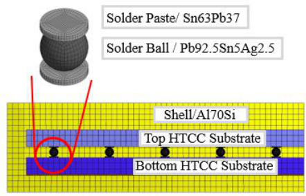
DESCRIPTION OF T/R MODULE The middle part of T/R module is composed of top and bottom rectangular HTCC substrates with the same size (see Figure 1). The bottom HTCC substrate has two symmetrical cavities with a depth of 1mm. The top and bottom HTCC substrates are connected by CBGA solder joints. The diameter of the solder ball is about 0.8mm and the material is Pb92.5Sn5Ag2.5. The diameter of the solder paste is about 0.8mm with a thickness of 0.1mm and the material is Sn63Pb37. The solder joints are evenly distributed, and the distance between them is about 3- 6 times the diameter of the solder ball. The peripheral packaging parts are shell and cover plate respectively. The shell and the bottom HTCC substrate are welded by SAC305 solder
Intelligent Human Systems Integration (IHSI 2022): Integrating People and Intelligent Systems https://openaccess.cms-conferences.org/#/publications/book/978-1-7923-8988-7 with a thickness of 0.1mm. The thickness of cover plate is 0.4mm, and its material is TC4. The shell and cover plate are connected by laser welding.
Figure 1. Cross-sectional view of the T/R module
Figure available in the original PDF paper.
EXPERIMENTAL TEST Interlaminar Shear Strength Test of HTCC Substrate
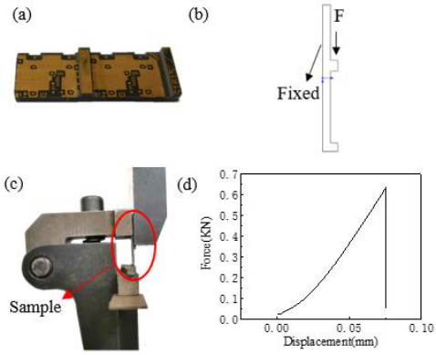
HTCC substrate is made by laminating and co-firing multilayer ceramic blanks printed with circuit graphics at high temperature(Zhang et al. 2021). The substrate should have sufficient mechanical strength, such as the bonding strength between substrate layers. It is found that transverse cracks occur between layers of HTCC substrate after reflow soldering, so it is necessary to carry out the test of Interlaminar shear strength HTCC substrate. A rectangular protrusion is made on the middle of the plane of HTCC substrate(see Figure 2(a)). The microcomputer controlled electronic universal testing machine is used to test the shear strength. The displacement loading speed is 0.5mm/min. The sample is vertically fixed by the shear fixture(see Figure 2(b)), and the protrusion is completely pushed off with a vertical downward force. The force and displacement curve in this process can be obtained(see Figure 2(d)).
Figure 2. Interlaminar shear strength test of HTCC substrate:(a) the shear sample of HTCC substrate;(b) mechanical principle figure;(c) test figure;(d) the force and displacement curve
Intelligent Human Systems Integration (IHSI 2022): Integrating People and Intelligent Systems https://openaccess.cms-conferences.org/#/publications/book/978-1-7923-8988-7
The failure peak force and shear area during this process are recorded. Ten groups of repeated experiments are conducted. It can be calculated that the Interlaminar average shear strength HTCC substrate is 34.153Mpa.
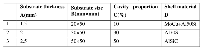
Orthogonal Experimental Design Several factors such as substrate thickness, substrate size, cavity proportion and shell material are selected for analysis (see Table 1).
Table 1: Parameter setting Cavity proportion
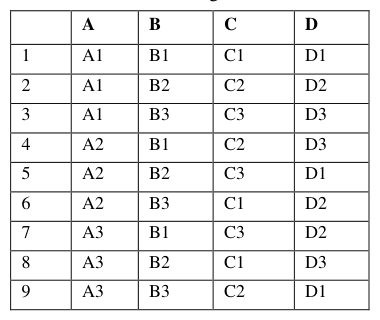
In order to reduce the number of tests, the orthogonal table is selected to arrange the tests (see Table 2).
Table 2: Orthogonal test A B C D
FINITE ELEMENT SIMULATION The thermal stress during reflow soldering of T/R module is studied by finite element thermo-mechanical coupling method. Taking orthogonal test 2 as an example to illustrate the simulation process.
Finite Element Model
Intelligent Human Systems Integration (IHSI 2022): Integrating People and Intelligent Systems https://openaccess.cms-conferences.org/#/publications/book/978-1-7923-8988-7
A quarter finite element model is established according to its symmetry(see Figure 3). In the transient thermal field, 0-300s is the heating stage, 300-1500s is the cooling stage, and T/R module is cooled to room temperature at 1500s. The coefficient of convection in the heating and cooling stages is 60.6W/(m2K) and 12.5 W/(m2K) respectively. The symmetrical plane of the model does not exchange heat with the surrounding environment. In the transient structural field, the center of the shell is fixed to prevent rigid displacement. In addition, the normal displacement of the symmetry plane is restricted.
Figure 3. Finite element model Plane Shear Stress Analysis of Bottom HTCC Substrate
The upper surface of the bottom HTCC substrate is in contact with the solder paste, and the lower surface is in contact with the SAC305 solder. Since the thermal expansion coefficient of SAC305 is greater than that of HTCC substrate (about 5 times), the expansion and contraction process of SAC305 solder will restrict the expansion and contraction of HTCC substrate, so it will generate horizontal shear stress on the HTCC substrate, and may cause shear failure of the horizontal plane of the substrate. It is the absolute value curve of plane Z shear stress during reflow soldering of bottom HTCC substrate(see Figure 4). Within 0-200s, the expansion of SAC305 solder plane in Z direction causes shear stress in Z direction of substrate, and the stress increases continuously. Within 200-349s, SAC305 solder melts, the substrate can expand and contract freely, and the shear stress is small. Within 349-1500s, SAC305 solder solidifies. At this time, the contraction of solder in Z direction is greater than that of HTCC substrate, resulting in Z-direction shear stress on the substrate. The shear stress in plane X direction of HTCC substrate is the same as the above analysis.
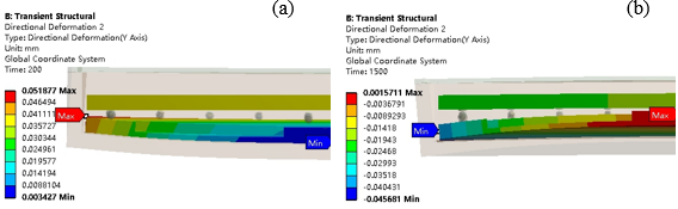
Stress Analysis of Solder Paste Sn63Pb37 CBGA solder joints connect the top and bottom HTCC substrates. Due to the deformation of the top and bottom substrates, CBGA solder joints will be subjected to tensile or compressive stress in the vertical direction. Under the state of tensile stress, the solder joints are easy to fall off. Within 0-200s, the SAC305 solder expands upward, so the bottom substrate warps upward. At this time, the solder paste is under pressure and will not fall off(see Figure 5(a)). Within 349-1500s, SAC305 solder solidifies. Therefore, the bottom substrate bends
Intelligent Human Systems Integration (IHSI 2022): Integrating People and Intelligent Systems https://openaccess.cms-conferences.org/#/publications/book/978-1-7923-8988-7 downward and the deformation at the edge is the largest(see Figure 5(b)). At this time, the solder paste is in the tensile state.
50
40
30
20
10
Shear Stress(MPa)
0
0 300 600 900 1200 1500
Time(s)
Figure 4. Shear stress curve of bottom HTCC substrate
Figure available in the original PDF paper.
Figure 5. Vertical deformation of top and bottom HTCC substrates (enlarged by 30 times):(a)at
200s;(b)at 1500s
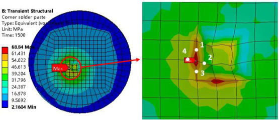
The solder paste Sn63Pb37 falls off in the tensile state during cooling stage. According to the above analysis, the corner solder joints has the largest deformation and tensile stress. In the cooling stage of reflow soldering, the stress of the corner solder paste increases until it is stable. It is a cloud diagram of the residual stress when the corner solder paste is cooled to room temperature(see Figure 6). It can be seen that a large stress is generated in the contact area with the solder ball. In order to avoid stress concentration at the junction of elements, the average value of the Middle stress of the four side lines at the stress concentration point is taken as the maximum stress of the solder paste.
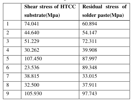
RESULTS AND DISCUSSIONR As described in part two above, several factors such as substrate thickness, substrate size, cavity proportion and shell material are selected for orthogonal experimental design (see Table 3).
Intelligent Human Systems Integration (IHSI 2022): Integrating People and Intelligent Systems https://openaccess.cms-conferences.org/#/publications/book/978-1-7923-8988-7
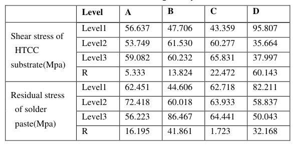
Table 3: Orthogonal stress table Residual stress of Shear stress of HTCC substrate(Mpa) solder paste(Mpa)Figure 6. Residual stress of corner solder paste at 1500s According to the uniformity and comparability of the orthogonal table, the average value of each factor can be calculated (see Table 4). For HTCC substrate, the sequence of factors that influence the shear stress is D-C-B-A. The theoretical optimal solution obtained from the orthogonal table is A2B1C1D2, and the calculated stress value is 22.853Mpa, which is less than the shear strength of the substrate. So this combination can be taken. For the residual stress of solder paste, the sequence of factors is B-D-A-C. The optimal solution is A3B1C1D3, and the calculated stress value is 32.212Mpa, which is less than the tensile strength of solder paste.
CONCLUSION
The experimental test and finite element thermo-mechanical coupling analysis are carried out in this paper. The main conclusions are as follows.
1) The horizontal shear stress of HTCC substrate due to thermal mismatch will weaken the bonding strength between layers, resulting in substrate cracking.
Intelligent Human Systems Integration (IHSI 2022): Integrating People and Intelligent Systems https://openaccess.cms-conferences.org/#/publications/book/978-1-7923-8988-7
2) The deformation of the top and bottom substrates will cause tensile or compressive stress to the CBGA solder joints. In the state of tensile stress, it is easy to cause the solder joints to fall off, resulting in interconnection failure. 3) Combined with the analysis of the above orthogonal table, the shell material D has a great influence on the stress of the HTCC substrate and solder joint. With increasing of thermal expansion coefficient of the material, the deformation degree of the HTCC substrate increases. The second factor is the substrate size B. when the size of the whole module is larger, the expansion and contraction degree will be greater
Table 4: Range analysis Level A B C D
REFERENCES
Chen, C., Hou, F., Liu, F. et al. (2017), “Thermo-mechanical reliability analysis of a RF SiP module based on LTCC substrate.” Microelectronics Reliability, 79, 38-47. Chong, S.C., Wai Leong Ching, E., Pei Siang, S.L. et al. (2020). Demonstration of
vertically integrated POP using FOWLP approach. IEEE 70th Electronic Components and Technology Conference, 873-878. Depiver, J.A., Mallik, S., and Amalu, E.H. (2020), “Effective solder for improved thermomechanical reliability of solder joints in a ball grid array (BGA) soldered on printed circuit board (PCB).” Journal of Electronic Materials, 50, 263-282. Kong, D., Zhang, L., and Yang, F. (2017), “Fatigue life prediction of SnAgCu-X solder joint
based on anand model.” Transactions of the China Welding Institution, 38, 17-21. Li, Y., Zeng, Y., Dong, D. et al. (2018). Reliability improvement of CBGA solder ball joint in LTCC-based SiP module. 19th International Conference on Electronic Packaging Technology, 656-661. Tian, Y., He, X., and Hang, C. (2014), “Influence of the hybrid BGA residual stress after
reflow on the thermal cycling reliability.” Journal of Mechanical Engineering, 50, 86- 91. Zhang, X., Chen, N., Wu, J. et al. (2021), “Rapid fabrication of surface microstructures on AlN HTCC substrate by chemically assisted laser ablation.” Ceramics International, 47, 27598-276.
Intelligent Human Systems Integration (IHSI 2022): Integrating People and Intelligent Systems https://openaccess.cms-conferences.org/#/publications/book/978-1-7923-8988-7
LISTED IN THE AHFE DIGITAL BOOKSTORE CATALOGUE
Explore the complete digital volume
Intelligent Human Systems Integration (IHSI 2022): Integrating People and Intelligent Systems
Read this individual research paper free through the original publisher, or explore the full digital proceedings book.
ISBN 978-1-7923-8988-7
Explore this ISBN in the AHFE Bookstore ↗Listed in the July 2026 bookstore catalogue; search by ISBN to confirm current availability · Digital book purchase optional