Marian Wnuk (2026). Electromagnetic Compatibility Analysis Of Automotive Vehicles. In: Advances in Human Factors of Transportation. AHFE Open Access, vol. 224, pp. 559–569. https://doi.org/10.54941/ahfe1007884
Automotive safety systems can be broadly divided into two categories: active and passive. Active safety systems are designed for prevention – they prevent accidents by warning the driver of a potentially dangerous situation or by helping them maintain control of the vehicle. Passive safety systems, on the other hand, aim to limit injuries resulting from an accident should one occur. The first group includes, among others: The following systems are available: ABS (Anti-lock Braking System), which prevents the wheels from locking during braking; ACC (Adaptive Cruise Control) - cruise control with automatic speed adjustment depending on the road conditions and maintaining a safe distance from vehicles in front; ESC (Electronic Stability Control) - an electronic stability control system; BLIS (Blind Spot Information System), which informs about the presence of other vehicles in the blind spot; LDW (Lane Departure Warning), which warns against lane departure; AEB (Automatic Emergency Braking), which is an emergency braking system; NVS (Night Vision System), which assists the driver when driving at night; RSR (Road Sign Recognition), which is a road sign recognition system; and TPMS (Tyre Pressure Monitoring System), which monitors tire pressure. Passive safety systems, in turn, include systems that control the operation of airbags and seatbelts, protecting against whiplash injuries during impacts, the Child Safety System (CSS), and the Pedestrian Protection System (PPS), which reduce the severity of injuries sustained by children and pedestrians during accidents. This paper presents the results of research on the response of a selected type of airbag activation.
The use of electronics in cars dates back to the 1970s, in the form of electronically controlled ignition systems. At that time, these systems operated independently of other vehicle systems and were responsible for contactless ignition. Improving comfort, and above all, vehicle safety and efficiency, along with reducing environmental impact, has driven the development of electronics and increasing the number of electronic components in cars. Electronic systems and their components are now more efficient, compact, and affordable, which is why electronics permeate the entire vehicle, and their applications in motor vehicles are constantly expanding. Subsequent electronic systems introduced after controlled ignition included electrohydraulic automatic transmission control, anti-lock braking (ABS), and fuel injection systems. The efficient operation of these systems required the exchange of information, an example Received February 25, 2026; Revised April 9, 2026; Accepted April 27, 2026; Available online July 20, 2026
560 Wnuk of which is the TD signal from the ignition system, which was essential for the L-Jetronic injection system. Later, more and more systems began to interact with each other. An example would be an engine control unit that blocked gear changes or ignition timing during anti-skid control, or a change in ignition timing during gear changes in an automatic transmission. Each signal then required a separate electrical wire, which contributed to the increased number of electrical cables in cars. Not only drive control systems but also multimedia information systems, comfort systems, and driving safety systems require networks of connections and interactions. Many electronic systems would not function without exchanging extensive data. The scope of automotive electrical and electronic testing is constantly expanding due to technological advances and increased concerns and requirements for driving safety and comfort. The increasing use of control, radio transmission, and steering systems in vehicles requires testing for electromagnetic compatibility. Considering the properties of electrical equipment and phenomena occurring in automotive electrical networks, particularly the occurrence of large voltage and current pulses and the large number of connections, it can be concluded that there is a possibility of conductive disturbances to certain electronic components due to inductive and capacitive coupling or interference from radiated emissions. The aim of this work is to analyse the electromagnetic compatibility of electronic systems in automotive vehicles.
OVERVIEW OF ELECTRONIC SYSTEMS IN MODERN CARS Microprocessor systems interact with each other in a precisely defined manner (Figure 1). High-end cars have up to 100 microprocessor systems, while lower-end cars have around 30. Current automotive systems commonly utilize advanced technologies such as electronics and information technology, replacing electromechanical, analog, and mechanical solutions. Electronic systems are reliable, easily configured, and relatively inexpensive. Therefore, they have good applications in control systems responsible for real-time algorithm execution, such as gearbox or engine control, as well as, for safety reasons, in critical systems such as suspension and braking control.
Drive systems
Multimedia
Engine Transmission
Phone Navigation
CAN High Speed Central control module Tuner TV FlexRay
Brakes Throttle
Radio Player CD/DVD
Safety systems CAN Low Speed on-board computer Door Roof air conditioning tracking Lighting
Driving comfort systems LIN Sensors Executive elements
Figure 1: Schematic diagram of the electronic systems of a modern car.
Figure available in the original PDF paper.
Electromagnetic Compatibility Analysis of Automotive Vehicles 561 Data Transmission Systems
In automotive vehicles, data transmission systems are used to connect electronic systems and control devices. Depending on the manufacturer and its requirements, various transmission systems have been developed. Network criteria depend on numerous parameters, such as the amount of data transferred and its transmission speed. Powertrain and safety systems place the greatest demands on networks, while comfort and body systems pose less stringent requirements.
CAN Bus The CAN bus is the most commonly used data transmission system. The bus is a two-wire bus made of twisted-pair copper wires. There are three types of CAN networks:
CAN – A – data transfer rate of approximately 10 kbit/s, used for diagnostic purposes and found in ride comfort systems and body equipment,
CAN – B (Low Speed CAN) – data transfer rate up to 125 kbit/s, used in ride comfort systems and body equipment,
CAN – C (High Speed CAN) – data transfer rate up to 1 Mbit/s, used for connections requiring quick response to events, e.g., drivetrain and brake control devices.
A single CAN network can support up to 35 control devices. Vehicles using a CAN bus typically use a linear topology (meaning that stations are connected to the bus at different points), but a star topology (stations are connected to a single point) can also be used.
LIN Bus The LIN bus is used where the network does not require high data transfer rates. It is used for driving comfort systems and body equipment. It is a simpler and less expensive solution than the CAN bus. Devices on the bus are connected using the master-slave principle.
One master device controls slave device. LIN allows for data transmission at speeds of approximately 20 kbit/s over distances of up to 40 m. A single network allows for the creation of up to 16 communication points. The LIN bus has been used in lighting control systems, driver and passenger seat adjustments, mirror control, and door and window opening and closing systems, among other things. Each slave device is assigned an address. The LIN network validates and responds to messages after detecting its own address and ruling out errors, although stations continuously monitor the data transmission process.
MOST Bus The MOST bus is used to create fiber-optic connections between multimedia devices in automotive vehicles. It has a single ring structure, in which all devices
562 Wnuk are simultaneously connected to the previous device (input) and the next device (output). Control signals, audio, and video signals can be transmitted via the MOST interface. Digital audio and video devices operate at a clock frequency of 44.1 kHz, and data transmission can occur at the same frequency. This enables synchronous, real-time transmission.
The MOST bus uses message-oriented addressing, enabling all devices to receive information simultaneously. In a MOST network, the most important device is the master device, i.e., the device performing the primary function. The maximum throughput does not exceed 21.1 Mbit/s. The MOST bus has three operating states:
sleep mode – no data transmission, no devices are operating;
standby mode – devices are ready for operation, system functions are unavailable.
operating mode – devices are operating, all system functions are available.
Byteflight Bus The Byteflight bus is a fiber-optic data transmission network used in vehicles for active and passive safety systems. It enables bidirectional communication at transmission rates up to 10 Mbit/s. Control devices are connected in a star structure, with a connector between them enabling connection to other networks and blocking the transmission of erroneous and invalid data. Information transmission can be event-dependent and time-controlled. Data on the bus is updated every 250 µs, with synchronization intervals – SYNC. After synchronization, counters located at the nodes begin counting time slots from 0 to 255. When a slot reaches the value of the identifier for which there is a current transmission response, the specified information is transmitted. After the transmission is complete, the device counters continue counting from the point where the process was stopped.
MEASUREMENT OF RADIATED AND CONDUCTED EMISSIONS Currently, basic vehicle safety equipment primarily consists of airbags and three-point seatbelts with pretensioners. The higher the vehicle’s class, the more airbags it has. These elements are essential primarily in the event of a frontal collision with an obstacle, to protect the driver and passenger from striking the steering wheel, dashboard, or windshield. In the event of a lower- speed collision, seat belts alone are sufficient. However, in a higher-speed collision, airbags are necessary.
An airbag consists of three basic components:
an activation system – containing a digital microprocessor and a piezoelectric sensor,
a gas generator – responsible for inflating the airbag, containing an igniter and solid fuel,
a flexible container – a bag made of nylon-cotton or polyamide fabric impregnated with neoprene rubber.
Airbags can be categorized based on their mounting location:
Front airbags – driver and passenger
Side airbags
Curtain airbags
Knee airbags The location of airbag system components in cars may vary slightly, but it consists of an airbag, a control module, side and front sensors, and explosive charges to detonate the airbags.
Front airbags are used to reduce head and chest injuries in a frontal collision. They prevent the driver from hitting the steering wheel and the passenger from hitting the dashboard or windshield.
Side airbags, along with seat belts, restrain the body of vehicle occupants during a side impact. Once the sensors trigger a signal, the airbags inflate, protecting the driver and passengers from injuries primarily to the chest, arms, shoulders, hips, and pelvis. They are typically located in the seatbacks or doors. Unlike front airbags, they have a much faster inflation time and have a capacity of approximately 10–20 liters. The side airbag module cannot be removed. It is attached to the seat frame with a bracket and consists of an inflator, airbag, and canister.
Curtain airbags complement seatbelts and side airbags, which restrain the driver and passenger during a side impact. In the event of an impact exceeding certain limits, the curtain airbags inflate immediately to mitigate the effects of the accident, particularly in the head and shoulder areas.
Types of curtain airbags:
ITS (Infratable Tubular Structure) – the airbag is a completely sealed sleeve, located in the front pillar and roof edge.
Curtain airbags, in the form of a curtain, extend along the roof edge and cover the entire side windows.
In the event of a head-on collision and a predetermined vehicle deceleration, a signal is sent from sensors mounted in durable bodywork components to the control unit, releasing an ignition current. This current flows to the detonator and gas generator. For safety reasons, the driver’s airbag uses a spiral cable, which provides greater contact reliability. In the event of a collision, the control system must determine the severity of the impact and determine whether seat belts will be sufficient to ensure safety or whether airbag deployment will be necessary. During an incident, at least one of the sensors must close additional contact.
Depending on the vehicle manufacturer, various types of sensors are available: a roller impact sensor and a spring-loaded inertial mass impact sensor.
Once the current reaches the primer, it detonates in a gas generator containing a gas-generating substance. The gas inflating the airbag is purified and cooled. Airbag systems vary in their readiness and inflation times, depending on the manufacturer. Approximately 30 milliseconds after the collision, the gas generator begins the airbag inflation process, and the inflated
564 Wnuk bag ruptures the shielding material at pre-determined locations. Within the next several seconds, the bag is filled with gas (most often nitrogen, less frequently carbon dioxide). The main component of the gas is sodium azide. It is a white crystalline powder with toxic properties. An electrical impulse flowing through the spiral cable decomposes the substance, producing nitrogen gas. The chemical reaction taking place in the gas generator
first reaction initiated by the impulse NaN3 -> 2Na+3N2
second reaction
10Na+2KNO3 ->K2 O+5Na2O+N2
final reaction K2 O+Na2O+SiO2
After approximately 54 ms, the bag is inflated, and the vehicle no longer moves, unlike the driver and passengers. After approximately 80 ms, the driver strikes the airbag with a force several times greater than its actual weight. The final process is the release of gas through openings located on the underside of the airbag.
Test Bench Components
Driver Airbag
Airbag Installation Station
Airbag Deployment Controller
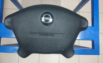
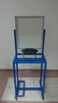
Figure 2: Driver airbag - tested system.
The test was performed on the driver’s front airbag, removed from an OPEL and FORD vehicle.
To remotely detonate the airbags, it is essential to properly prepare the location where the procedure will be performed. Pyrotechnics are most often detonated in a vehicle or in a container made of tires. The safe distance from the load is approximately 10 meters. Due to the need to conduct the tests, an airbag deployment stand was used. The airbag was attached to the frame using a special holder to prevent the airbag from moving or deploying in the wrong direction. The AIRBAG deployment panel was used to remotely
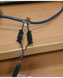
Electromagnetic Compatibility Analysis of Automotive Vehicles 565 deploy the airbag in a safe environment. The left wire connects the airbag to the system, while the right wire is connected to a 12V power supply.
When the system is connected and powered, the yellow indicator light illuminates. The green indicator light illuminates when the yellow button is pressed if the circuit is properly connected. The red indicator light illuminates when the red button is pressed while holding the yellow button. The yellow button is used to check circuit continuity, and the red button is used to detonate the charge.
A special connector adapted to the sockets located on the airbags was used to connect the system to the airbag.
An oscilloscope is a measurement tool used to observe and measure the parameters of distorted electrical waveforms. Choosing the right oscilloscope setup not only allows you to measure the parameters of the distorted waveform but also determines the dynamic and static characteristics of electronic devices. It is also possible to measure their phase shift and dynamic resistance.
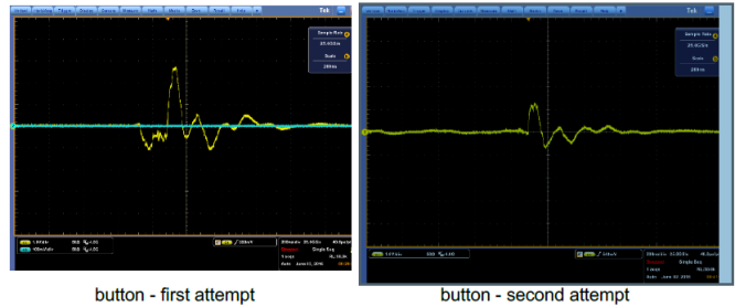
After properly connecting the detonation system to the airbag and power supply, it is necessary to verify its correct operation. This is done by pressing and holding the yellow “circuit continuity” button. After doing this, the signals shown in Figures 5 can be observed on the oscilloscope. Each figure shows a separate button press. It can be observed that these signals are not identical, although they are similar in shape; these are transients used to check the continuity of the system.
Figure 6: Signal after pressing the “CIRCUIT CONTINUITY”.
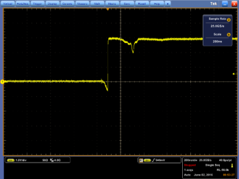
Airbag Deployment After checking the circuit, you can begin deploying the airbags. To do this, hold down the yellow button and press the red “detonation” button. The following signals for two airbags are recorded on the oscilloscope screen.
Electromagnetic Compatibility Analysis of Automotive Vehicles 567 The first signal is most likely incorrect. You may notice that an additional voltage of approximately 3 V appeared during the measurement. This may be caused by the transducer entering a different range or by a charge accumulating in the power supply.
First Second
Figure 7: Airbag deployment signal.
The second cushion signal is valid. We can calculate the frequency spectrum from both signals using a fast Fourier transform.
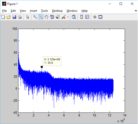
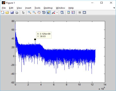
Calculating the Signal Spectrum Using Matlab, the signals were converted to frequency spectra. This was accomplished using the “fft” function. Below is the .m file used to calculate and plot the spectrum and convert the X-axis from the number of samples to frequency.
Figure 8: Frequency spectrum of the first measurement. Amplitude.Figure 9: Frequency spectrum of the second measurement.
CONCLUSION
Vehicle electronic systems are exposed to interfering signals originating from outside sources, such as radio communications, road infrastructure, or other vehicles. Such signals occur over a wide frequency range and at varying levels. Therefore, reliable electromagnetic compatibility testing is crucial, as it is necessary to determine compliance with quality and safety requirements.
Electromagnetic interference belongs to a large group of unwanted signals that always accompany useful signals. Significant causes of interference include: the occurrence of couplings in electrical circuits, short circuits and damage to components or systems, thermal instabilities, instability of connections and systems, random and periodic voltage changes in electrical circuits, and the penetration of signals from one circuit to another, for example, between signal transmission lines.
By analysing the operation of the vehicle’s electronic and electrical equipment, it can be assumed that the main components responsible for the disturbances include: the electronic airbag and air conditioning control system, the ignition and injection system, the electronic suspension, steering, and braking systems, the alternator with its voltage regulator, the electric motors of auxiliary devices, signalling devices, computers with sensors, and ICT and radio communication devices. After testing the airbag system, it can be concluded that the system generates interference that is harmful to the vehicle’s systems. To prevent interference, it is necessary to consider ways to limit this interference or reduce its impact on the operation of the vehicle’s electronic systems.
Electromagnetic Compatibility Analysis of Automotive Vehicles 569 As can be seen, a band appears in both spectra at 3.123 GHz. This frequency is most likely where interference generated during the airbag deployment process can be expected.
REFERENCES
A. Herner, H.J. Riehl: Elektrotechnika i elektronika w pojazdach samochodowych, WKŁ, Warszawa 2011. G. Dyga , G. Trawiński: Diagnostyka układów elektrycznych i elektronicznych,
WSiP, Warszawa 2014 IEEE 802.1Qbu—Bridges and Bridged Networks—Amendment 26: Enhancements for Frame Preemption. 2016. Available online: (accessed on 7 July 2024). IEEE 802.1Qbv—Bridges and Bridged Networks—Amendment 25: Enhancements
for Scheduled Traffic. 2015. Available online (accessed on 7 July 2024). J3016; Taxonomy and Definitions for Terms Related to Driving Automation Systems for On-Road Motor Vehicles. SAE: Pittsburgh, PA, USA, 2018. Park, C.S.; Park, S.K. Performance Evaluation of Zone-Based In-Vehicle Network
Architecture for Autonomous Vehicles. Sensors 2023, 23, 669. Wang, S.; Zhou, H.; Zhao, H.; Wang, Y.; Cheng, A.; Wu, J. A Zero False Positive Rate of IDS Based on Swin Transformer for Hybrid Automotive In-Vehicle Networks. Electronics 2024, 13, 1317. http://www.dsod.p.lodz.pl/materials/EwP03_A01.pdf https://pl.wikipedia.org/wiki/ABS_(motoryzacja) https://en.wikipedia.org/wiki/Emergency_brake_assist https://en.wikipedia.org/wiki/Autonomous_cruise_control_system - http://brainonboard.ca/safety_features/active_safety_features_ebfd.php - http://neon.lofis.net/SsangYong/Service_Manuals/Kyron/Kyron_2_Chasis_008_02_004.
pdf http://ntm.wimii.pcz.pl/download/Uklady_bezpieczenstwa_czynnego_w_pojazdach.
pdf https://en.wikipedia.org/wiki/Lane_departure_warning_system - https://en.wikipedia.org/wiki/Driver_Monitoring_System http://www.iee.lu/products:transportation:seat-belt-reminder https://www.ngk.de/pl/technika-w-szczegolach/sondy-lambda/podstawowa-wiedzao-spalinach/obwod-regulacji-lambda/ -
LISTED IN THE AHFE DIGITAL BOOKSTORE CATALOGUE
Explore the complete digital volume
Advances in Human Factors of Transportation
Read this individual research paper free through the original publisher, or explore the full digital proceedings book.
ISBN 979-8-950676-00-0
Explore this ISBN in the AHFE Bookstore ↗Listed in the July 2026 bookstore catalogue; search by ISBN to confirm current availability · Digital book purchase optional