Marian Wnuk (2025). Antenna technology in energy recovery systems. In: Human Factors in Software and Systems Engineering. AHFE Open Access, vol. 181, pp. 34–49. https://doi.org/10.54941/ahfe1006392
Nowadays, we observe dynamic technological progress. Often, due to the multitude of responsibilities, we are not aware of the conveniences that modern technology gives us. Modern man cannot imagine life without the possibility of using radio communication systems, including mobile telephony. Systems for obtaining electricity from phenomena occurring in the natural or industrial human environment are known under two names: energy harvesting and energy scavering. Both of these names refer to the same phenomena and methods. Sometimes in the literature the use of these names depends on the nature of the energy being processed. The name energy scavering is used when the type of energy source and its efficiency are not known, while energy harvesting is used when the source of potential energy is well described and regular.The dynamic development of applications requiring autonomous energy sources favors the rapid development of EH technology. The main area of application of EH is wireless sensor networks (WSN), where the energy demand of a single autonomous node depends on the current operating mode. In the standby state, the demand for electricity usually does not exceed several μW, and during measurement it does not exceed 100 μW. The greatest demand occurs during information transmission and ranges from 0.1 to 1 mW. Such energy demand values clearly indicate the possibility of using EH generators as additional power sources for smartphones.Another area of application of EH technology are systems for recharging batteries used in larger measurement systems where there are other traditional ways of charging batteries.One of the fundamental problems that arise when analyzing the possibility of using electromagnetic radiation as a source of recovered energy is the issue related to the assessment of the field strength distribution in the area of operation of the designed system. Knowledge of this distribution allows the designer to assess the degree of land cover. Therefore, every designer faces a serious problem of selecting an appropriate propagation model that will best describe the reality created by the designed system.An important aspect when analyzing the possibility of using electromagnetic radiation as a source of recovered energy is the proper selection of antenna technologies that can be used for the above application. In this chapter of the study, microstrip antennas are proposed for the above purpose.The work presents a designed measurement antenna that can operate from 500 MHz to 7.6 GHz, the operating bandwidth is 7.1 GHz,
Systems of obtaining electricity from phenomena occurring in the natural or industrial human environment are known under two names: energy harvesting and energy scavenging. Both of these names refer to the same phenomena and methods. Sometimes in literature the use of these names depends on the nature of the energy being processed. The term energy scavenging is used when the type of energy source and its efficiency are unknown, while energy harvesting is used when the source of potential energy is well described and regular (Alibakhshi-Kenari, 2015).
The dynamic development of applications requiring autonomous energy sources is conducive to the rapid development of EH technology. The main area of application of EH are wireless sensor networks (WSN), where the energy demand of a single autonomous node depends on the current operating mode (Abhishek, Singhal, 2019). In the standby mode, the demand for electricity usually does not exceed a dozen or so µW, and during the measurement it does not exceed 100 µW. The greatest demand occurs during the transmission of information and ranges from 0.1 to 1 mW. Such energy demand values clearly indicate the possibility of using EH generators as additional power sources for smartphones. Another area of application of EH technology is the systems for charging batteries used in telecommu- nications systems. Modern EH systems exist on both a macro and a micro scale (Minatti et al., 2014). The obtained energy densities range from a single µW/cm3 in the case of using electromagnetic phenomena to 15000 µW/cm3 in the case of using photovoltaic phenomena. The main sources of energy used in this type of generators are the natural environment of man and man
himself. In the case of humans, two types of energy are primarily used: kinetic and thermal, and the environment allows the use of radiation energy in addition to the ones. Different phenomena are used in each of these types of energy. In case of kinetic energy, these are piezoelectric, electromagnetic and electrostatic phenomena. In the case of thermal energy, thermoelectric phenomena, and in case of radiant energy, the photovoltaic phenomenon and RF radiation. These phenomena have very different energy yields. Table 1 shows the average energy densities obtained for the most frequently used EH generators. To ensure the correct functioning of a given electronic device or, as a rule, it is necessary to modify (condition) the electrical quantity generated by the EH converter to provide the appropriate supply voltage. An obvious required feature of all the electronics used in the EH generator structure is the extremely low power requirement. In addition, to effectively use EH sources, making a given electronic or telecommunications device independent of traditional power sources, in addition to the low-energy operating regime provided for it, it is necessary to ensure an optimal method of energy transfer.
Table 1: Summary of obtained energy densities for the most popular EH generators.
This means that the power electronic conditioning systems used in the EH generator should ensure the implementation of some form of impedance matching between the EH converter and the load, guaranteeing the transmission of the highest possible power under given conditions [Michalski].
CHARACTERISTICS OF SELECTED WIRELESS COMMUNICATION SYSTEMS The civilizational requirements of a modern man are characterized by the need for quick access to information. Therefore, there is a need to send information between any points, both in the area of the selected country, as well as on a global scale [Akyildiz].
These tasks are performed by radiocommunication systems ensuring two- way wireless communication with mobile stations moving in the area covered by the system of base stations, with the area covered by the system being
36 Wnuk
divided into sub-areas usually shown schematically in the drawings in the form of hexagons with base stations in their centers.
There are generally four categories of urban development:
dense and high buildings in the city centers of large cities,
relatively low buildings in medium and small towns and suburban buildings,
housing estates of low-rise houses around densely built-up areas,
rural area, surrounding built-up areas.
The listed categories of environments differ significantly in the conditions of radio wave propagation. These conditions depend on the position of the antenna of the base station and the mobile station in relation to each other and the surrounding buildings [Buxton, Fujimoto].
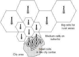
Figure 1 shows an example of the division of the area into cells of various sizes depending on the category of development. The reason for the division of the area covered by the system operation into cells is the insufficient capacity (understood as the maximum number of mobile stations simultaneously served by the system with a specific bandwidth) of the system with a single high-power base station covering the entire area. The problem of optimizing radio coverage comes down to determining the best possible locations for base stations, and this is not an easy task, because many variables related to this location must be considered here: power used by base stations, antenna characteristics, or heights of buildings and the related limitations.
Figure 1: Different cell sizes in radio communication systems.
Such numerous radio communication systems can be treated as a source of “electromagnetic smog” at the same time. There are also (albeit timidly) components for converting the ubiquitous electromagnetic smog into electricity, which has high hopes, e.g. manufacturers of mobile phones and other portable devices that have a chance to become virtually independent of standard power sources. One of the ways of dividing mobile radiocommunication systems is the degree of their complexity and the possibility of providing services (Abhishek, Singhal, 2019).
Antenna Technology in Energy Recovery Systems 37
Table 2: Frequency ranges of selected wireless communication systems.
Table available in the original PDF paper.
Band Destiny Alternative
Reception Frequency The Power of Designation Radiation [MHz] [W]
Paging systems - 434, 449,750 25 Trunked systems - 417-420, 458–459 0,5 P-GSM 900 Primary GSM 900 935÷960 Transmitter classes
communications According to this classification, we can divide them into:
paging systems,
wireless telephone systems,
trunked systems,
mobile phone systems,
38 Wnuk
satellite telephone systems,
wireless access systems to local computer networks.
The above systems operate in different frequency ranges (Table 2).
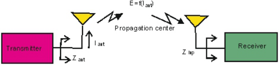
The classic radio communication system is shown in Figure 2.
Figure 2: Layout of the radio communication system.
For such a system, the value of the signal level at the receiver input can be written using the Friis relation:
λ
Equation reproduced from the original PDF.
where: PT - the power dispatched at the transmitter antenna, PR - power dispatched to the receiver antenna, r - distance between antennas, GR - gain of the receiving antenna, GT - z gain of the transmitting antenna. An important parameter characterizing each base station and mobile terminal is the maximum power of their transmitters for individual classes of devices, which is specified in the specifications of the GSM and UMTS systems. The power classes of the base station transmitting systems are presented in Table 2. In the case of GSM 900 base stations, eight classes with maximum values of the power supplied to the coupling element have been defined. The step between successive power classes is 3 dB, i.e. the value of the maximum power for each class decreases twice with the next increase in the class number.
For the GSM 1800 and GSM 1900 systems, 4 standard ranges have been prepared with lower maximum powers compared to the GSM 900 system. The final selection of the power class of the base station in the GSM system depends, among others, on the size of the cell and the traffic generated in it. Currently, base stations of class 5 and higher are most often used due to the dense structure of the distribution of base stations caused mainly by heavy traffic. The GSM standard also introduced power classes for stations covering a limited area of land - microcells and picocells.
Antenna Technology in Energy Recovery Systems 39
In the case of the GSM system, due to the impulse nature of the transmitters’ operation and guard periods at the beginning and end of the slot lasting 28 µs, the average value of the power of the signals emitted by the antennas is much lower than the maximum value. For comparison, in the case of the UMTS system, due to continuous transmission, the difference between the maximum and average power values is much smaller. Powers radiated by portable terminals are shown in Table 3. The electromagnetic energy radiated by these systems can also be treated as “electromagnetic smog”, because we are usually dealing with non-directional radiation or radiation with a wide range of characteristics. It is one of the most readily available sources of energy on Earth. We can treat this radiation as a source for generating electricity and classify it as “energy harvesting”. The construction of power sources did not fail to take advantage of this.
Table 3: Power classes of mobile terminals in GSM and UMTS systems.
Table available in the original PDF paper.
Power Classes of Mobile Terminals in the GSM System
Power Classes of Mobile Terminals in the UMTS System 1 - 1 W 1 W 1 2 W 2 8 W 0,25 W 0,25 W 2 0,5 W 3 5 W 4 W 2 3 0,25 W 4 2 W - - 4 0,125 W 5 0,8 W - - - -
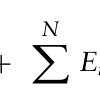
The frequency (spectrum) of the measured electromagnetic field, it is assumed that at any time, for a selected point in space, there is one vector E and one vector H, which are linearly polarized, and their size is determined by the sum of all spectral bands of spatial components. This can be represented by the following formula:
Equation reproduced from the original PDF.
Where: E0 – electrostatic field strength, Ei – intensity of the i-th fringe, ωi – pulsation of the i-th band, ϕi – phase of the i-th band. The formula is universal to use, it is possible to replace the E component with the H component, then we will obtain a formula defining the temporal variation of the magnetic field.
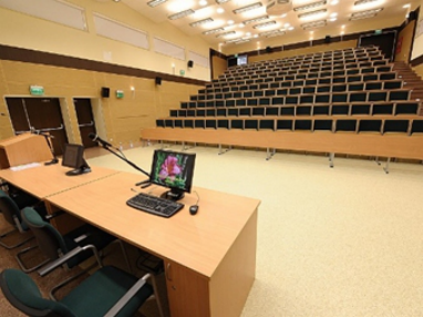
If we consider participants in university lecture halls or conferences, Figure 3, for whom a telephone or smartphone is a natural element of modern civilization, the average power occurring in these facilities and coming from the above-mentioned devices may be about 200 W.
It is a value that can be treated as a source of clean energy, i.e. energy harvesting.
40 Wnuk
Figure 3: View of a typical lecture hall.
THE ROLE OF THE ANTENNA IN THE RADIO COMMUNICATION SYSTEM One of the most important elements of radio communication systems and energy recovery systems is the antenna. Its task is to transform the input current into an electromagnetic field and radiate it to the surrounding space (transmitting antenna) or vice versa (receiving antenna). The antenna is therefore a device that adjusts the wave guides to the free space. Due to its location between the transmitting or receiving devices and the space, the requirements for the antenna are imposed both by the conditions of propagation of electromagnetic waves in space and by the influence of the antenna as an element of the device on its operation.
A general look at the antenna and its role in the radiocommunication system, where it is treated as an integral part of it, allows for the formulation of the following requirements:
the antenna is an element of the transmitting-receiving system, the radiation mechanisms of which should consider the surrounding elements and structures,
must be designed considering propagation effects - polarization, collective reception, etc.
compatible with environmental conditions - radiation characteristics adapted to the serviced zones, considering nearby objects,
integration of the antenna with the platform on which it is installed must be ensured - considering the influence of the environment, e.g. the operator’s hand, body and possible harmful effects,
user-friendly and reliable in operation - limited electromagnetic impact on the user, high mechanical reliability.
A full model of the antenna in real conditions should consider propagation conditions, local environmental conditions, system configuration, signal-to- noise ratio, operating band, physical properties of the antenna itself, its compatibility with the technology of the device it works with and the way it is operated by the user [Kong]. In addition, such factors as the ability to adapt to changing frequency ranges, the type of transmitted information, and
Antenna Technology in Energy Recovery Systems 41
modulation are some of many factors considered in the design of antennas for radio communication systems [Born].
The above-mentioned wireless communication systems have been developing very intensively since the end of the 20th century, which is one of the greatest opportunities for equipment manufacturers to win markets. The rapid growth of mobile services is observed all over the world. The number of terminals is growing mobile personal communication systems, DECT and GSM/UMTS mobile telephony, data transmission devices, wireless computer networks, WLAN/WiFi and others, which exceeds many times the number of users of mobile communication systems, because most of them have more than one type of mobile device. This growing number of mobile devices also increases the level of electromagnetic energy radiated to the environment. We can treat this radiation as a source of electricity and classify it to the “Energy harvesting” group. For antenna designers, there is an unprecedented opportunity to create compact, electrically small antennas implemented in technologies that meet specific requirements. One of the conditions is work on small surfaces, in close proximity to the user’s body, maintaining the assumed frequency band and efficiency of approx. 90%. This problem has been solved for many years, it is associated with the miniaturization of electronic equipment, where in most cases conventional antenna solutions cannot be used.
The design of antennas for mobile devices is moving towards structures: small, light, with a flat profile, mounted directly on the housings of antenna systems. They are usually geometrically complicated solids with different conductivity and losses, working in a time-varying, generally ill-defined environment. This plays an important role in the operation of antennas, and therefore in the processing (transmission/reception) of electromagnetic signals.
The evolution towards miniaturization of mobile radio communication system terminals, possible due to the reduction of the size of electronic systems, limiting their power consumption and increasing their computing capabilities, contributes to the reduction of physical dimensions of antennas mounted in these devices. Reducing the geometric dimensions of the radiator, however, has a negative impact on the electrical parameters of the antenna, such as the working band width and energy gain. The desired radiation pattern and the coverage of the proper operating band are obtained for the size of the antenna comparable to the wavelength.
Antenna designers must therefore find the right compromise, reconciling small dimensions of the antenna while ensuring its proper property.
SMALL ELECTRICALLY MULTIBAND ANTENNAS People currently use telecommunications devices in various conditions: at home, at work, in the car, on the move, often away from fixed telecommu- nications infrastructure, expecting reliable connections. In such cases, wireless devices are especially useful [Cao]. Thanks to technological progress in the construction of electronic components, the size of devices in the RF range is constantly decreasing, hence the expectation of similar limitations in
42 Wnuk
the size of antennas. However, this is at odds with the electrical requirements of small size antennas. Modern wireless devices are expected to operate in several frequency bands, covering several bands: GSM, IEEE 802.11 (Wi- Fi, Wireless Fidelity), IEEE 802.16, Wi-Max (Worldwide Interoperability for Microwave Access) and GPS (Global Positioning System).
From an engineer’s point of view, an antenna that works untuned in the 824 MHz to 2500 MHz range can be considered as single-band, but also as wide-band. In the terminology of wireless devices, an antenna that covers more than one frequency range is considered multi-band. For example, an antenna covering two separate frequency bands (824÷960) MHz and (1710÷1990) MHz is considered a quad band antenna because it covers the GSM 800, GSM 900, GSM 1800 and GSM 1900 systems.
The popularity of microstrip antennas is due to a simple reason - they have many advantages (and relatively minor disadvantages) thanks to which they can be used for various purposes. In their favor, the following features can be included (Yaghjian, 2014; Gao et al., 2015):
allow miniaturization of the antenna,
simplicity and low cost of mass production,
small dimensions and low weight,
can be used on surfaces of various shapes, including spherical surfaces,
hiding the operating frequency,
resistance to mechanical action when attached to a rigid surface,
universality - they can be designed to produce various types of characteristics and polarizations, depending on the induced operating mode and the specific shape of the radiator [Kong].
Despite the above-mentioned disadvantages of antennas, their numerous advantages have led to the fact that they are widely used in civil as well as military systems.
THE CONCEPT AND DESIGN OF THE ANTENNA FOR THE ENERGY HARVESTING SYSTEM The designed antenna used to measure the properties of the electromagnetic field should be characterized by parameters such as: directivity, energy gain, input impedance and bandwidth.
In this case, a logarithmic-periodic antenna was used as the antenna for the energy harvesting system, which is frequency-independent, its characteristic impedance Z0 changes logarithmically as a function of frequency [Balanis]. According to the principle of Rayleigh-Helmholtz reciprocity generalized by Carson to the case of antennas, the relationship between the parameters of an antenna operating in the conditions of transmitting and receiving is defined (Radavaram, Pour, 2019). When identifying point sources with antenna terminals, we can state 0the principle of reciprocity as follows. If the current I am flowing through the terminals of antenna 1 produces the voltage U at the terminals of antenna 2, then the same current I flow through the terminals of antenna 2 will produce the same voltage U at the terminals of antenna 1. This is a common formulation of the principle of reciprocity
Antenna Technology in Energy Recovery Systems 43
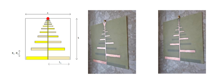
for antennas. The principle of reciprocity is valid regardless of the distance between the antennas, and therefore also in the near field. An important conclusion resulting from the principle of reciprocity is the possibility to measure the parameters of a transmitting antenna using it as a receiving antenna. The LPDA microstrip antenna uses two powered radiating surfaces that are located on either side of the laminate. The elements of the antenna (Figure 4) are arranged laterally and alternately, they form dipoles, which are powered by a symmetrical cable with a constant wave impedance in such a way that there is a 180
phase shift between adjacent dipoles
Figure 4: LPDA antenna with dimensions and physical view.
The antenna power point is marked red. The electromotive force that develops in an antenna is determined by Faraday’s law:
Equation reproduced from the original PDF.
where: eH–is the electromotive force induced in the antenna µ0–is the magnetic constant.
Three variables are responsible for the length of the dipoles and their distance between each other: the scale factor τ, the distance factor σ and the angle α – the opening of the microstrip structure. The distance factor defines the distance measured in wavelength between successive dipoles (Khaleghi et al., 2019).
The relationship between τ and σ is given by the following relationship:
Equation reproduced from the original PDF.
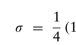
4 (1 −τ) ctg α (4)
From this relationship we can determine the angle α:
ctg α = 4σ 1 −τ (5) In order to make the calculations, it was necessary to determine the value of the coefficients, using the constant directionality curve, the coefficient
44 Wnuk
τ = 0,78 has been selected. Then the value of the coefficient σ was calculated. Then, the value of the coefficient was calculated. These values were selected to obtain the assumed antenna gain of at least 5.5 dBi, in our case it is σ = 0, 139.
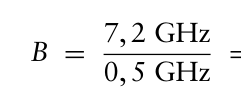
According to the assumption, the antenna should operate in the band from fmin=500 MHz, to fmax=7.6 GHz. Thus, the coverage factor is:
Equation reproduced from the original PDF.
0, 5 GHz = 15.2 (6) Then, the next step in accordance with the algorithm is to determine the active part of the operating band, which is
Bar = 2, 041864 (7) Based on the calculations, the minimum number of dipoles was determined: N = 12, 71 ≈13.
To be able to cover the band more effectively, the number of dipoles has increased to 14 dipoles. The next step was to calculate the length of the dipoles and the distance between them. The results obtained are only geometrical quantities determined for free space and do not consider the dielectric parameters. The dielectric used to build the antenna has a key influence on its parameters. Therefore, when choosing it, careful attention should be paid to its thickness (t), substrate height (h) and relative dielectric permittivity (εr), as well as the loss of the dielectric material (tgδ).
Dielectric permittivity is a fundamental parameter of the substrate, because it determines the resonant frequency of the antenna. The selection of the εr value is also important, as it affects the radiation efficiency. In practice, materials constituting the substrate of the antenna are used, whose dielectric constant is in the range 2.2 ≤εr ≤10. The increase in the thickness of the laminate h affects the width of the operating frequency band. Unfortunately, the widening of the working band with this method is very limited, because the increase in the thickness h also affects the increase in the phenomena associated with the generation of the surface wave. Too much thickness of the dielectric can lead to a situation where the antenna stops radiating. Of course, the limits of the allowable thickness of the dielectric and its dielectric permittivity depend on the frequency with which the radiator will operate. From the discussion above, it can be seen that the conflicting requirements as to the parameters of the dielectric must be reconciled. The only unequivocal parameter is the dielectric loss, and it should be less than tgδ < 0.001.
To consider the parameters and characteristics of the antenna in the calculations, it is necessary to use an analytical method based on electrodynamic modeling. The appropriate choice of the analytical method is forced by the model of the constructed or analyzed antenna. Due to the combination of field and circumferential problems in these antennas, they require the use of complex analytical methods.
The FDTD (Finite-difference time-domain method) method, a finite difference method in the time domain, is such a calculation method that allows for calculations of the sought-after quantities with high accuracy
Antenna Technology in Energy Recovery Systems 45
(Wang et al., 2020). Using the Fourier transform of the field in the vicinity of the antenna (near zone), the radiation pattern in the far zone is calculated. This method is used in the simulation program CST Microwave Studio [Akyildiz].
The laminate used for the substrate was the FR-4 substrate, the thickness of which was h = 1.6 mm, dielectric permittivity coefficient εr was 4,3. The thickness of the copper tracks is 0,035 mm.
After the optimization simulations, the following dimensions of the antenna were obtained. They are presented in Table 4.
Table 4: Geometric dimensions of the measuring probe.
The analysis of the model was made in the CST Microwave Studio program, this software allows for a specialized 3D EM simulation for high frequencies. The program has high efficiency, making it frequently chosen to carry out this type of simulation, moreover, it allows for accurate and fast analysis in the high frequency range for antennas, filters with single- or multi-layer structures.
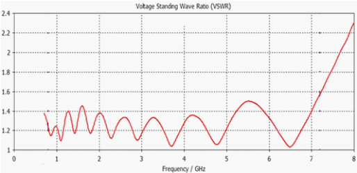
The WFS value depends on the ratio of the load impedance to the wave impedance of the line, the values that it can take are from unity upwards, a value of 1 means that all the power that will be delivered to the antenna will be radiated by it into the ether, it is an ideal case where the wave impedance of the line is the same as the impedance of the antenna.
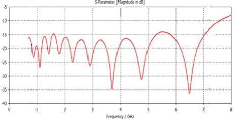
Figure 5: Standing wave factor of the antenna in the 0.8–7.6 GHz band.
46 Wnuk
The figure above shows a graph of the obtained standing wave ratio, it was obtained in the band from 500 MHz to 7.6 GHz. The lowest value was reached at frequencies of 3.71; 4.77 and 6.5 GHz, with the highest at 7.6 GHz. The values achieved in the whole band are acceptable for the designed antenna. The values achieved in the whole band are acceptable for the designed antenna. The reflection coefficient is a parameter closely related to the WFS coefficient. If parameter S11 is 0, it means that all the power delivered to the antenna has been reflected and returned to the receiver. The higher the value of the coefficient, the more power will be radiated from the antenna. For commonly used antennas, the value of the coefficient should be less than –10 dB, for values below the antenna operating band are defined
Figure 6: Parameter S11.
The figure above shows a graph of the S11 parameter value, in the assumed band it reached the required value (less than –10 dB). Ripples and numerous notches result from the resonant frequencies of the antenna, when the antenna works at the resonant frequency, it achieves much better values of the S11 parameter.
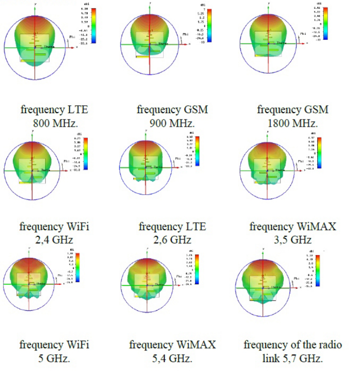
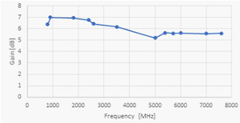
The radiation pattern is the distribution of energy radiated into space by the antenna, it shows the distribution of the electric field strength. The further part of the paper presents the spatial characteristics, as well as the characteristics in the vector plane⃗H for selected systems in which the designed probe could be used for measurements The maximum difference in gain is 1.81 dB at 0.9 [GHz] and 5.0 [GHz]. The half-power angle for the H vector plane is shown in Figure 7 was 139
, while for the E-vector plane the half-power angle was 77
.
For the frequency of 900 MHz, the half-power angle for the H-vector plane was 139
, while for the E-vector plane, the half-power angle was 77
.
For the frequency of 1800 MHz, the half-power angle for the H-vector plane was 110
, while for the E-vector plane, the half-power angle was 83
.
For the frequency of 2.4 GHz, the half-power angle for the H-vector plane was 107
, while for the E-vector plane, the half-power angle was 77
.
For the frequency of 2.6 GHz, the half-power angle for the H-vector plane was 121
, while for the E-vector plane, the half-power angle was 106
.
For the frequency of 3.5 GHz, the half-power angle for the H-vector plane was 111
, while for the E-vector plane, the half-power angle was 81
.
Antenna Technology in Energy Recovery Systems 47
Figure 7: Spatial characteristics of the antenna.Figure 8: Probe gain vs. frequency.
For the 5 GHz frequency, the half-power angle for the H-vector plane was 179
, while for the E-vector plane, the half-power angle was 85
. For the frequency of 5.4 GHz, the half-power angle for the H-vector plane was 110
, while for the E-vector plane, the half-power angle was 83
.
48 Wnuk
For the frequency of 5.7 GHz, the half-power angle for the H-vector plane was 125
, while for the E-vector plane, the half-power angle was 71
.
For the frequency of 6 GHz, the half-power angle for the H-vector plane was 161
, while for the E-vector plane, the half-power angle was 78
. The results obtained are satisfactory, the profit obtained is significantly above the assumed value.
CONCLUSION
One of the fundamental problems that arise when analyzing the possibility of using electromagnetic radiation as a source of regenerated energy is the issue of evaluating the distribution of field strength in the area of operation of the designed system. Knowledge of this distribution enables the designer to assess the degree of land cover. Therefore, each designer faces a serious problem of selecting the appropriate propagation model that will best describe the reality created by the designed system.
An important aspect when analyzing the possibility of using electromagnetic radiation as a source of regenerated energy is the proper selection of antenna technology that can be used for the above application. In this chapter of the study, microstrip antennas have been proposed for the above purpose.
The work presents a designed antenna that can operate in the range from 500 MHz to 7.6 GHz, the operating bandwidth is 7.1 GHz, The assumed value of the wave coefficient in the entire band does not exceed 2. The antenna was to have a gain of at least 5 dBi, the presented characteristics show that for most cases the gain value is above 6 dBi, the lowest observed gain value was 5.19 dBi obtained for the frequency of 5 GHz. The antenna has a large value of the half-power angle, which means that it will very well receive the electromagnetic field reaching it, in the case of using the antenna as a measuring probe, it will greatly simplify the measurements, because it will not be necessary to direct the antenna very precisely at the tested object, but only roughly direct it towards the object.
The antenna has the characteristics of a broadband antenna, which say that with the increase in frequency (which was almost tenfold) there were no significant changes in the shape of the spatial characteristics. Of course, there were some distortions and changes in antenna gain, but they are minimal. It can be visible that the antenna has a wider operating band than assumed at the beginning of this work, the S11 parameter reaches favorable values from the frequency of 700 MHz to the frequency of 7.5 GHz.
REFERENCES
Alibakhshi-Kenari M., Naser-Moghadasi M. “Novel UWB Miniaturized Integrated Antenna Based on CRLH Metamaterial Transmission Lines” AEUE Elsevier- International Journal of Electronics and Communications, Volume 69, Issue 8, August 2015, Pages 1143–1149. Abhishek J, Singhal R, “Vertex-Fed Hexagonal Antenna with Low Cross- Polarization Levels” Advances in Electrical and Electronic Engineering 2019, vol. 17, iss: 2 pp. 423–435, iss: 4 p. 138.
Antenna Technology in Energy Recovery Systems 49
Cao Y. F; Zhang X Y; Xue Q. Compact Shared-Aperture Dual-Band Dual- Polarized Array Using Filtering Slot Antenna and Dual-Function Metasurface IEEE Transactions on Antennas and Propagation, Publication Year: 2022, Page (s):1120–1131 04. Gao X., Han X., Cao W.-P., Li H. O., Ma H. F., and Cui T. J., “Ultrawideband
and high-efficiency linear polarization converter 427 based on double v-shaped metasurface,” IEEE Transactions on Antennas and Propagation, vol. 63, no. 8, pp. 3522–3530, 2015. Khaleghi S. Mousavi S, Moradi G, Shirazi R. S. Jafargholi A. Microstrip Line Impedance Matching Using ENZ Metamaterials, Design, and Application Transactions on antennas and propagation, Vol. 67, No. 4, April 2019. Liu Q. S., S. Sun, and Chew W. C., “A potential-based integral equation method for
low-frequency electromagnetic problems,” IEEE 415 Transactions on Antennas and Propagation, vol. 66, no. 3, pp. 1413–1426, 2018. Minatti G., Faenzi M., Martini E., Caminita, P. De Vita, D. Gonz’alez-Ovejero, M. Sabbadini, and S. Maci, “Modulated 424 metasurface antennas for space: Synthesis, analysis and realizations,” IEEE Transactions on Antennas and Propagation, vol. 63, 425, no. 4, pp. 1288–1300, 2014. Radavaram S, Pour M., Wideband Radiation Reconfigurable Microstrip Patch
Antenna Loaded With Two Inverted U-Slots IEEE Transactions on Antennas and Propagation, Vol. 67, No. 3, March 2019 1501. Wang J, Li Y, Jiang Z. H., Ming-C. T. Tang S., Zhou Z, Chen Cheng Z. Qiu N. Wei, Metantenna: When Metasurface Meets Antenna Again IEEE Transactions on antennas and propagation, Vol. 68, No. 3, March 2020. Yaghjian D., “Reflections on Maxwell’s treatise,” Progress In Electromagnetics
Research, vol. 149, pp. 217–249, 2014. 338 420 Electromagnetic Field Theory.
LISTED IN THE AHFE DIGITAL BOOKSTORE CATALOGUE
Explore the complete digital volume
Human Factors in Software and Systems Engineering
Read this individual research paper free through the original publisher, or explore the full digital proceedings book.
ISBN 978-1-964867-57-1
Explore this ISBN in the AHFE Bookstore ↗Listed in the July 2026 bookstore catalogue; search by ISBN to confirm current availability · Digital book purchase optional