Felix Dreger, Sarah Kuhlmann, Frank Weichert, Gerhard Rinkenauer (2024). 4-DOF Robotic Arm Simulator for Machine Operator Training and Performance Evaluation: Engineering Design and Experimental Validation. In: Human Factors in Robots, Drones and Unmanned Systems. AHFE Open Access, vol. 138, pp. 37–46. https://doi.org/10.54941/ahfe1005006
Robotic crane operators are essential in construction or forestry (e.g. excavator or forest harvester cranes), where their performance significantly impacts efficiency and safety. Training for crane operators relies on high-fidelity simulations to develop high skill levels. However, productivity analyses revealed large variances among machine operators, with disparities by up to 40%. Therefore, skill acquisition must be advanced through improved training methods, which are based on a deeper understanding of sensory-motor control of the crane. Typically, used training simulators provided by the original equipment manufacturers (OEMs) lack access to e.g. detailed joystick data as well as lack the possibility to modify the simulations to include real-time performance feedback. To address this limitation, a robotic crane simulator was collaboratively designed by the Leibniz Research Centre for Working Environment and Human Factors and the Chair of Computer Graphics from TU Dortmund. The simulator was evaluated within a pilot study with 36 participants who conducted 32 aiming movements with the simulated robotic crane. The results show skill improvements over time and the suitability of the simulator to analyse skill acquisition in robotic crane operations.
The robotic crane is the key machinery in various industries such as forestry, construction, or logistics, for example as part of forest harvesters or excava- tors. The skilful handling poses a significant control challenge to the machine operator which requires extensive and costly training (Hartsch et al., 2022). Machine operators are trained by experienced colleagues and in some cases in training centres (Lorenz et al., 2020). Nonetheless research in the forestry domain showed that the productivity of the machines can vary by up to 40% between different machine operators (Ovaskainen et al., 2004). This implies that (1) the current training has still potential to be improved and (2) oper- ator support systems on the machines are worthwhile to be introduced. To
improve operator performance, an analysis of the current machine opera- tor control challenges is necessary also to derive implications for training redesign and skill acquisition support.
Current training of machine operators use high fidelity simulators that are provided by the OEMs of the respective machines (Ranta, 2009). Alongside the hardware, software tools are provided which allow realistic simulation but only rudimentary data analysis (e.g. John Deere TimberSkills). The con- straints are coming from the high fidelity of the simulators that utilize similar hardware and software components to the real machine. Available data on operator performance is focussed on productivity measures such as m3/h. To analyse the sensory-motor control task of the machine operators, access to the control inputs is at topmost importance, however, not possible in most of the simulators. Furthermore, real-time feedback on critical control parame- ters is necessary for training and performance improvements. Simulators of OEMs do not allow flexible changes to the visualization of the simulation and thus limit adaptability and implementation of feedback. Therefore, in collab- oration, the Leibniz Research Centre for Working Environment and Human Factors and the Chair of Computer Graphics from TU Dortmund designed a low-cost simulator based on the open access robotic framework “Open Manipulator” (Robotis Inc., Korea). The simulator ought to be designed such that skill acquisition of the sensory-motor task could be assessed and different real-time performance feedback designs tested. In the following, firstly the simulator set-up will be described, and secondly, a short pilot study demonstrating the usefulness of the simulator for skill evaluation will be presented.
ROBOTIC CRANE SIMULATOR MODELLING Simulator fidelity can broadly be categorized by the physical, the perceptual and the behavioural fidelity (Pool, 2012). A simulator thus can be classi- fied as how realistic one of the categories is matched. Physical fidelity refers to how well the physical world such as the used controls or displays are resembling the real machine. Perceptual fidelity refers to how well the per- ception in the simulator matches real world perceptual properties. Lastly the behavioural fidelity refers to how well the observed behaviour in the sim- ulator matches real world behaviour. The designed simulator was focussed to assess the behavioural changes while training. The focus was to achieve a behavioural valid platform to get insights into the training of the control of the robotic crane. The simulator designed, consists of different hardware components (e.g. PC, screens) and software components (e.g. visualisation) to create a suitable testing platform that can feedback operator performance.
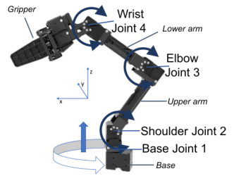
Robotic Crane Characteristics The robotic crane was based on the open manipulator framework (Robotis Inc., Korea) and adapted to a CH8 knuckle boom (cf. WARATAH Harvester and Forwarder Cranes, 2020). The crane length including base was adapted to 10.19 m and the joint range was extended (cf. Figure 1). The robotic arm
4-DOF Robotic Arm Simulator for Machine Operator Training and Performance Evaluation 39 had a base joint that allowed for a slewing angle of 342
degree. The rota- tional joints (shoulder, elbow, wrist) had a range of 172
degree. The gripper was closed and not used.
Figure 1: Robotic crane joint description based on the original robot-arm (left, robotis Inc., modified by author) and the redesign of the dimensions of the simulated robotic crane (right).
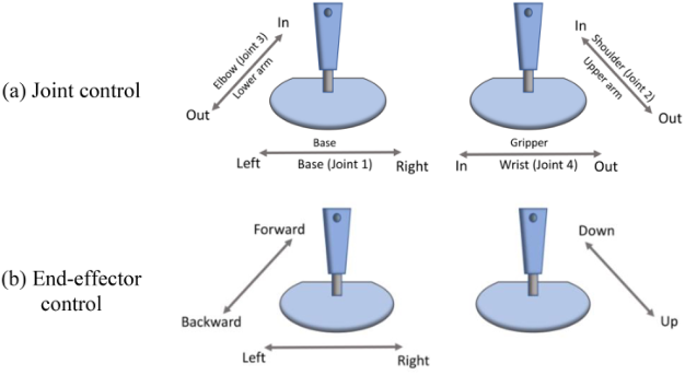
Control Schemes and Kinematic Design The robotic crane can be operated with two control schemes (see Figure 2). The joint velocity or the end effector velocity control scheme. The default control scheme is the joint velocity control (Figure 2a). With the joint velocity control scheme each joystick axis maps to a specific joint of the robotic crane and controls the velocity of the joint movement. This is referred to as forward kinematic. With the end effector control scheme each joystick axis maps to a movement direction of the end effector in 3D Cartesian space (Figure 2b). The joysticks thus control the velocity of the end of the kinematic chain, whereas an algorithm computes the required joint positions.
Figure 2: Two control schemes of the simulation, (a) the joint control and (b) the end- effector control. The arrows describe effect on the joint movement in (a) crane ling and (b) end-effector movement in 3D.
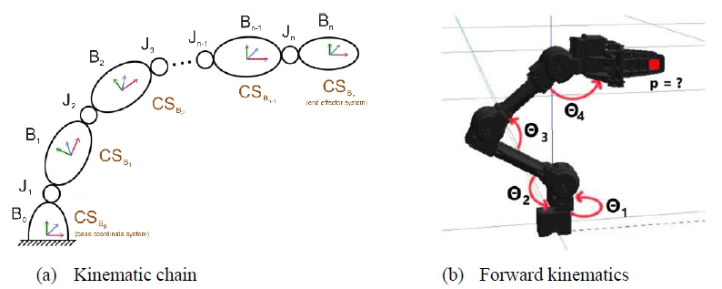
Kinematic Model In the simulation environment, all parts of the robot crane must be dynami- cally virtualized. Therefore, the gripper arm is formalized as a finite kinematic chain. This consists of a finite number of rigid bodies connected by a finite number of joints (Orin et al., 1979). A movement of the entire model can be described by movements of the individual joints (Stone, 1987). Formally, a gripper arm R is described by an ordered set R =
Bo, J1, B1, . . . , Jn, Bn
, where the joint Ji connects the two bodies Bi−1 and Bi. In addition, each joint has one degree of freedom, representing the number of directions in which it can move. Figure 3a shows the kinematic chain with its coordinate systems. The first body of the chain forms the base and also references the base coor- dinate system. The last body is specified as the end effector. Each body Bi is represented in its own coordinate system CSBi.
Figure 3: Visualisation of the kinematic chain (according to (Vukobratovi´c & Kir´canski, 1986)) and the forward kinematics.
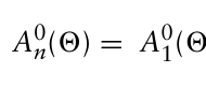
Since a direct sequence of transformations is too complex due to the many degrees of freedom of the gripper arm and therefore inefficient, it is simplified according to the Denavit-Hartenberg convention (Stone, 1987). Figure 3b visualizes the forward kinematics. The positions of all rotational joints 2 = (21, . . . , 2n)T are known, while the position p is sought. The coordinate system of a body Bi is represented in relation to the previous body in the kinematic chain using homogeneous matrices. This requires four Denavit-Hartenberg parameters, which represent the physical structure of the bodies Bi and their relationships to each other (Kucuk et al., 2006).
A0
Equation reproduced from the original PDF.
n (2n) (1)
Equations and mathematical formulas are available in the original paper PDF.
with [Equation or mathematical symbol available in the original paper PDF]
[Equation or mathematical symbol available in the original paper PDF]
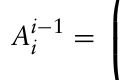
Ai−1
Equation reproduced from the original PDF.
Equations and mathematical formulas are available in the original paper PDF.
cos 2i −sin 2i cos αi sin 2i cos αi αi cos 2i sin 2i cos 2i cos αi −cos 2i sin αi αi sin 2i 0 sin αi cos αi di 0 0 0 1
4-DOF Robotic Arm Simulator for Machine Operator Training and Performance Evaluation 41
The result is the transformation of the end effector Bn relative to the base Bo. The coordinate system i refers to the body Bi. The parameter di also denotes the distance between two bodies. These four parameters are determined for each body and are represented by ordered sets or vectors.
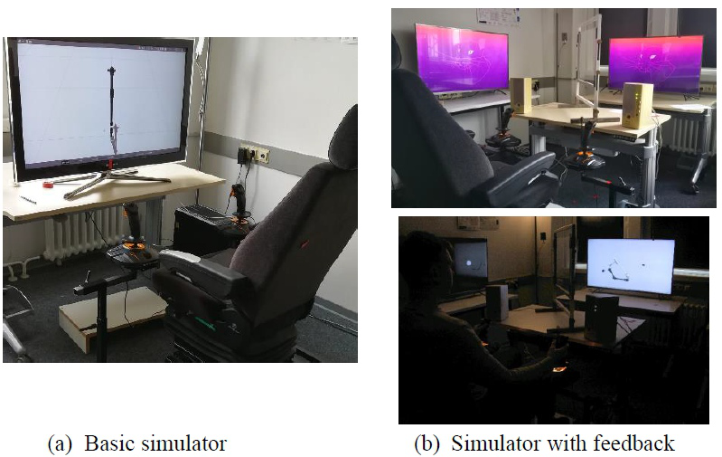
Hardware Architecture The simulator developed from a single screen setup (Figure 4a) to a multi- sensory test platform with two Xiao Mii 55-inch TV (Mi P1 55) screens and a Grammer Chicago truck seat (MSG 90.3 C) that was mounted on a metal frame holding two Thrustmaster joysticks (T.16000M FCS, see Figure 4). The core of the simulator is a powerful Robot Operating System (ROS) PC to which the two 55-inch screens are connected. Additionally, a third screen is connected for the examiner to monitor the experimental task. A semi- permeable mirror was placed on a table in front of the truck seat to present feedback in the operator’s field of view, allowing visual feedback to overlay the visualisation. Furthermore, two speakers for the presentation of auditory feedback, a head mounted eye-tracking system and an electroencephalograph (EEG) were connected to the ROS PC via a notebook (see Figure 4b).
Figure 4: Simulator development from (a) single screen without feedback setup to (b) multisensory test platform with feedback.
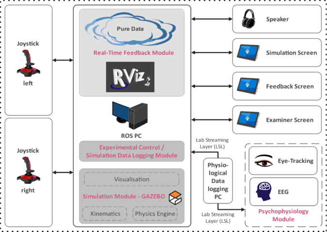
Software Architecture The software architecture is based on ROS. The ROS PC runs ROS, therefore integrating the real-time feedback module, the visualisation module, the input from the simulator’s joysticks and the experimental control (see Figure 5). The ROS PC is connected through Lab Streaming Layer (LSL) with the phys- iological data running and logging software of the EEG and the eye-tracker (Neon, Pupil Labs). The general simulation and software architecture were
built on the ROS based open-source framework “open manipulator” (Robo- tis Inc., Korea). The architecture was extended with ROS nodes that allow to control the robotic crane bimanually via the joysticks. For bimanual joystick use the built-in ROS joystick node was split into two nodes, each handling one joystick. The visualisation module comprised the software GAZEBO as main simulation of the robotic manipulator. The open manipulator framework can visualise objects through YAML/STL-based meshes rendered in GAZEBO for simulation. The outline of the robotic manipulator was adapted to the dimension of a crane of a forest harvester.
The feedback module of the simulator can provide auditory and visual real-time feedback. The auditory feedback is created with PureData a visual programming language for the design of computer-generated music. A feed- back node was implemented which subscribes to the 3D kinematic pose of the end effector of the robotic crane. The 3D kinematic pose of the robotic crane is used within this node to design and process movement feedback, which communicates via TCP with PureData. The data received from PureData is translated into a series of sinusoidal tones with overtones generating the audi- tory real-time feedback. The feedback is designed to provide the distance to the crane movement target arms’end effector.
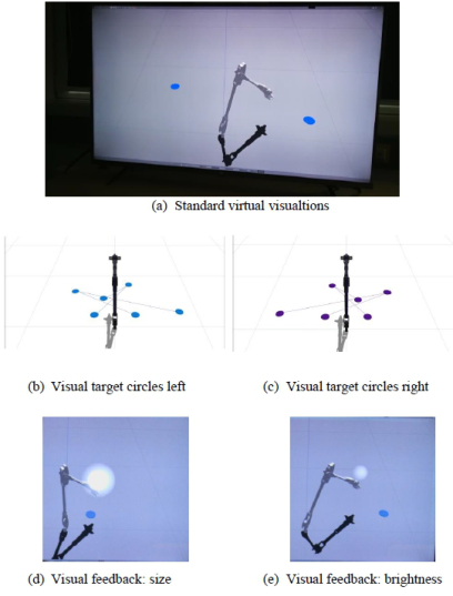
Visual feedback is generated using the 3D visualisation tool for ROS, RViz, which can visualize the entire robot and single geometric objects such as cubes and spheres. Therefore, a node was implemented, which subscribes (receives) to the kinematic pose of the end effector of the robotic crane in 3D space. The kinematic pose is then used to design feedback that controls the bright- ness and size of a 3D sphere, which is visualized in RViz (cf. Figure 6c, d). Manipulating the 3D object in RViz is possible during runtime.
Figure 5: Software and hardware architecture of the robotic crane simulator.
4-DOF Robotic Arm Simulator for Machine Operator Training and Performance Evaluation 43
The experimental control was implemented with a ROS node in which the target stimuli were randomized, and mesh objects spawned within the Gazebo environment (e.g., circles in Figure 6). Furthermore, the node records time series data such as joint positions, end effector position, joystick inputs, and the runtime of the robotic manipulator. The experimental con- trol can also get and write the experimental conditions, participants ID, and experimental session.
Figure 6: Visualisation of the robotic crane and visual targets of the aiming movement task (a-c). In (d) and (e) visual feedback is provided.
Simulator Evaluation The suitability of the simulator for the analysis of performance and skill acquisition was assessed within a short, ethical approved, study with 36 (male = 20, female = 16) participants. Recruited participants were between 18 and 35 years old (M = 24.19 years; SD = 4.31 years).
Task Design and Procedure Participants had to execute 32 aiming movements with the simulated robotic crane. The designed task and targets of the aiming movements were derived from the work method two-sided felling in the field of forestry. A more detailed description can be found in (Dreger et al., 2023). The goal was to evaluate the suitability for the assessment of operator learning. The task of the participants was to tap alternatingly between the two present target circles. The task was derived from Fitts’ tapping
task (cf. Soukoreff & MacKenzie, 2004). The performance metrics move- ment time and accuracy measured as time from one target circle to another and distance to the target centre were used to evaluate learning. Four differ- ent target length were presented. The targets were mirrored so that the four targets required either a movement diagonally from left to right or vice versa. Thus, eight different target pairs were sequentially and randomized for each participant presented. For each target four movements were conducted.
RESULTS
The data was pre-processed with MATLAB R2021a and the statistical anal- ysis with R version 4.1.1. For the data analysis the mirrored target pairs with the same target distance were collapsed leading to four distances of the eight sequentially presented targets.
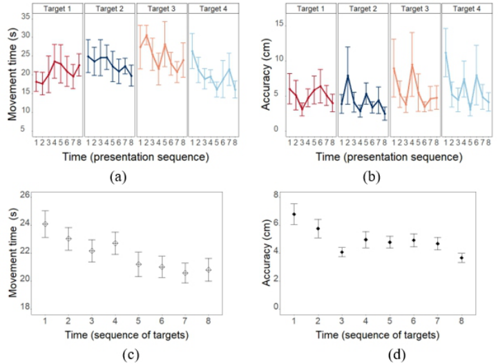
The measured movement times and accuracy of the movement across participants are shown in Figure 7. The statistical analysis showed that with time on task the movement time was significantly decreasing (F(5.27,184.33) = 2.43, p = .034, ηp2 = 0.07, Figure 7a). Similarly, the accu- racy was significantly improving with time on task (F(3.53,123.67) = 2.43, p = 0.034, ηp2 = 0.07, Figure 7b). The overall improvement across targets and participants is shown in Figure 7c and d.
Figure 7: Movement time and accuracy development with target sequence in a and b split for the four targets and aggregated across targets in c and d.
4-DOF Robotic Arm Simulator for Machine Operator Training and Performance Evaluation 45
CONCLUSION
In this study a low-cost simulator was developed to assess operator controlled aiming movements with a robotic crane. The pilot study results showed its suitability to assess human performance and learning progress in terms of movement time and accuracy. The simulator can provide auditory and visual feedback about critical control parameters and additionally derive meaning- ful performance and control skill metrics. Consequently, both the movements in simulation and the operator inputs to the joysticks can be parametrized. For instance, Dreger et al. (2023) conducted a detailed analysis of the oper- ator inputs through the joysticks to evaluate learning on two different time scales.
The versatile platform allows for flexible adaptation of the visualization and can thus be used to vary operator tasks, auditory and visual feed- back. The limited fidelity of the simulation environment, however, may limit the overall task representation of potential real-world scenarios. Therefore, the physical set-up can be improved in the future in terms of the control layout and 3D virtual environment. Overall, the simulation platform has the potential to serve the evaluation of operator training, mental load and attention.
ACKNOWLEDGMENT
This work was supported by the ERA-NET Cofund Action “ForestValue— Innovating the forest-based bioeconomy” and by Fachagentur Nachwach- sende Rohstoffe (FNR, Germany), Forskningsradet (The Research Council of Norway), VINNOVA, and The Swedish Innovation Agency. ForestValue received funding from the European Union’s Horizon 2020 research and innovation programme under grant agreement N
773324.
REFERENCES
Dreger, F. A., Chuang, L. L., & Rinkenauer, G. (2023). Analysis of learning the bimanual control of (tele) operating joint space controlled robotic arms with 4 degrees of freedom using the two-timescales power law of learning. Ergonomics, 0(0), 1–13. https://doi.org/10.1080/00140139.2023.2270784 Hartsch, F., Dreger, F. A., Englund, M., Hoffart, E., Rinkenauer, G., Wagner, T.,
& Jaeger, D. (2022). Positive and Negative Work Practices of Forest Machine Operators: Interviews and Literature Analysis. Kucuk, S., Bingul, Z., Kucuk, S., & Bingul, Z. (2006). Robot Kinematics: Forward and Inverse Kinematics. In Industrial Robotics: Theory, Modelling and Control. IntechOpen. https://doi.org/10.5772/5015 Lorenz, S., Helmert, J. R., Anders, R., Wölfel, C., & Krzywinski, J. (2020). UUX
Evaluation of a Digitally Advanced Human–Machine Interface for Excavators. Multimodal Technologies and Interaction, 4(3), Article 3. https://doi.org/10.3390/ mti4030057 Orin, D. E., McGhee, R. B., Vukobratovi´c, M., & Hartoch, G. (1979). Kinematic and kinetic analysis of open-chain linkages utilizing Newton-Euler meth- ods. Mathematical Biosciences, 43(1), 107–130. https://doi.org/10.1016/0025- 5564(79)90104-4
Ovaskainen, H., Uusitalo, J., & Väätäinen, K. (2004). Characteristics and Significance of a Harvester Operators’ Working Technique in Thinnings. International Journal of Forest Engineering, 15(2), 67–77. https://doi.org/10.1080/14942119. 2004.10702498 Pool, D. M. (2012). Objective Evaluation of Flight Simulator Motion Cueing Fidelity
Through a Cybernetic Approach [Technical University Delft]. https://resolver.tud elft.nl/uuid: e49e4ead-22c4-4892-bbf5-5c3af46fc9f5 Ranta, P. (2009). Added values of forestry machine simulator based training. Proceedings of the International Conference on Multimedia and ICT Education., 6. Soukoreff, R. W., & MacKenzie, I. S. (2004). Towards a standard for pointing device
evaluation, perspectives on 27 years of Fitts’ law research in HCI. International Journal of Human-Computer Studies, 61(6), 751–789. https://doi.org/10.1016/j. ijhcs.2004.09.001 Stone, H. W. (1987). Kinematic Modeling, Identification, and Control of Robotic Manipulators (Vol. 29). Springer US. https://doi.org/10.1007/978-1-4613-1999-3 Vukobratovi´c, M., & Kir´canski, M. (1986). Kinematics and Trajectory Synthesis of
Human Factors in Robots, Drones and Unmanned Systems
Read this individual research paper free through the original publisher, or explore the full digital proceedings book.
ISBN 978-1-964867-14-4
Explore this ISBN in the AHFE Bookstore ↗Listed in the July 2026 bookstore catalogue; search by ISBN to confirm current availability · Digital book purchase optional