Steven Vusmuzi Mashego, Timothy Laseinde (2023). Optimization of turbine generator through vibration damping for maximum service life in power plants. In: Human Factors in Software and Systems Engineering. AHFE Open Access, vol. 94, pp. 180–186. https://doi.org/10.54941/ahfe1003783
Power plant condition monitoring data is essential in identifying unscheduled maintenance needs. The data obtained from monitoring the condition of a power plant over numerous years of operation indicates that the primary reason for the failure of turbo generators due to vibrations is the misalignment of the turbine centreline. It is crucial to identify problems with steam turbines to prevent load losses and boost the operational reliability of a turbo generator. This paper presents the vibrational characteristics of a 500 MW turbo generator and the performance boost attained through optimized turbine maintenance. Shaft relative vibrations were analyzed at run-up at 500 rpm with no load and at 3000 rpm with approximately 420 MW. The study found that the highest absolute pedestal vibration levels were reduced by 8.5% as a result of maintenance optimization.
Since the invention of electricity, turbine generators, more commonly referred to as turbo generators (TGs), have been relevant. The size and configuration of a turbo generator (TG) determine the amount of vibratory energy it can produce, which depends on the speed at which it rotates, its size, and the TG design. In the course of the research, an exhaustive analysis was performed on the TG, which is close to its end of life, according to life cycle analysis.
The vibration signatures of the TG during its run-up, run-down, and steady-state operations were recorded and analysed. He data capture was carried out using the conventional approach to managing a TG set’s availa- bility, reliability, and maintainability. In the case of turbomachinery that has been overhauled or taken out of service for routine maintenance, this kind of vibration analysis is included as part of the quality assurance programs in place. Recent studies have also proposed the integrated use of some of these philosophies. Even though each of these philosophies proposes the develo- pment of maintenance plans from a different perspective, the integrated use of some of these theories has been suggested (Ramere and Laseinde, 2021). It is essential to recognize that they have the same goal: to ensure that the system continues to function correctly and maintain its integrity. The primary
Optimization of Turbine Generator Through Vibration Damping 181
objective of these philosophies is to devise an effective strategy for planning preventative maintenance. The primary emphasis is placed on monitoring the state of the system’s components and overall health to create a dynamic preventive schedule (Melani et al., 2019).
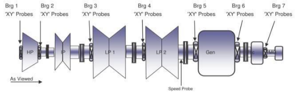
A recent study highlights the necessity of maintenance for steam turbi- nes which is of great significance to ensure the safe and stable operation of the machine. A TG set at a power station where the study was conducted consists of four-cylinder steam turbines connected to a 500-megawatt (MW) Generator. The TG train comprises seven bearing pedestals serving High Pressure (HP) turbines, Intermediate Pressured (IP) turbines, two Low Pressured (LP) turbines, a generator, and an exciter as the illustrated in Figure 1.
Figure 1: General arrangement of turbo-generator centreline train.
BACKGROUND
Turbo Generator (TG) Vibration In mechanically dynamic systems, vibrations are oscillations propelled by high torque. The force of inertia of moving parts within the system is the most common source of these oscillations in the system. Some components may be rotating or reciprocating (Vance et al., 2010). In the case of Turbo Generators (TG), the turbine rotors rotate while the steam inlet valves reciprocate. The dynamic load conditions are determined by the strength of the turbo gene- rator elements, such as when the turbo generator is passing through critical rotational speed during run-up or run-down (transverse vibration) and also when the turbo generator is operating in abnormal modes (torsional vibrati- ons). In the research, the criteria for acceptable specifications are defined in zones A and B, which usually should not exceed 1.25 times the boundary of A/B (ISO, 2009). The vibration zone boundaries for the TG set are explained under the background of this study.
Bovsunovskii (2014) explained that cracks in turbine rotors from failed service turbines spread through the system over several years. It is critical to monitor the vibrations of the TG machine during start-ups, regular opera- tion, and during system shutdown. To monitor relative vibrations, axial and radially positioned probes were installed on the bearing pedestals and tur- bine shaft. The probes are components that convert mechanical motions into electrical ones. The vibration values detected by the probes were to be displa- yed on the control room screen via a permanently installed signal processor.
182 Mashego and Laseinde
Vibration monitoring on the TG machine captured the machine’s state and condition.
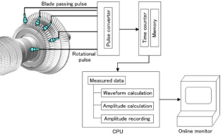
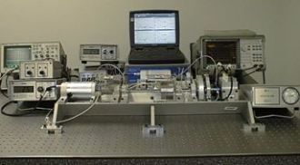
Vibrations negatively impact because they can cause downtime or secon- dary damage, increasing maintenance costs and revenue loss if not addres- sed promptly. Figure 2 depicts the schematic configuration of the Bently Nevada DSPi 408 multi-channel vibration monitoring system linked to the Siemens VM 600 protection rack, while Figure 3 depicts an ADRE 408 DSPi ]hboxMachinery. The DSPi equipment was used, and the on-site vibration signatures were captured and analysed accordingly.
The vibration signal frequencies can help diagnose rotor dynamics issues. Rotor imbalances often cause shaft whirling. Rotor imbalances often cause shaft-speed-coordinated whirling. Large synchronous vibration amplitudes usually indicate a problem with the rotor’s balance, according to Vance et al. (2010). As part of a performance evaluation, the pk-pk amplitude should be computed at the bearings, as Boyce (2012) recommended. The distance in microns from pick to pick is how vibration displacement is measured (m pk-pk).
Condition Monitoring of TG Condition Monitoring (CM) is conducted due to the increased demand for high-speed operation for the longer operational duration, reduced breakdo- wns and maintenance, higher productivity, and better safety considerations. Condition monitoring is the process of examining system parameters in the service to eliminate failures. It improves the availability and reliability of the plant. CM also includes monitoring different calculated parameters correla- ted with mechanical factors such as friction, strain, temperature, oil debris,
Figure 2: Schematic arrangement of the on-line monitoring vibration system (Tamura et al, 2014).Figure 3: ADRE 408 DSPi machinery (directindustry.com, 2020).
Optimization of Turbine Generator Through Vibration Damping 183
and system output to assess the machine’s state of safety (Harris and Piersol, 2002). The health consequences of rotating machines are known to have negative effects, including vibrations. Condition monitoring streamlines rou- tine maintenance to prevent major accidents and costly downtimes. Thus, TG must be monitored to guarantee reliability (Ramere and Laseinde, 2021; Gubran, 2015).
Vibration Zone Boundaries Understanding the vibration’s origin is the key to solving vibratory pro- blems (Zhu et al., 2017). According to the Intonational Organizational for Standardization (ISO, 2009), bearing housing or pedestal vibrations for large steam turbines and generators are grouped in rotational speeds and boundary zones. The typical measurement parameter for determining machine vibration intensity is velocity, and these measurements are used mainly during periodic vibration surveys or for diagnostic purposes (ISO, 2009). The rotational speed is measured in revolutions per minute (rpm), and the unit of measurement for the boundary zones is in millimeters per second (mm/s). Table 1 presents the evaluation zone boundaries measured in root-mean-square (rms).
Turbo generators with output power greater than 50 MW at an operational speed of 1500 rpm or 1800 rpm are in the first group. The second group is turbo generators at an operating speed of 3000 rpm or 3600 rpm. The boundary zones are divided into lower, mid, and high vibration levels. Low vibration levels are within acceptable vibration velocity, and high vibration levels are considered to be of significant magnitude to create harm to the TG set. For safety, the vibration alarm was set at 165 µm Pk-Pk and the trip value was set at 260 µm Pk-Pk for a 500MW TG set at a major power station in the southern region.
Table 1. Large turbo generators’ vibration velocity values for bearing housing or pedestals at zone boundaries.
Initially, the vibration levels of the shaft were recorded as the turbine- generator (TG) set was started up at a speed of 500rpm. Subsequently, the shaft vibration levels were measured when the TG set reached a steady-state condition, with a rotational speed of 3000rpm and no load. Lastly, the shaft vibration levels were recorded at a load of 421MW. These measurements were taken during the TG set’s return to service and compared to the data collected during the TG’s return to service after the retrofitting of the LP turbines.
184 Mashego and Laseinde
During the execution of an outage on the Turbo Generator (TG), the activity involved a modular replacement of the High Pressure (HP) and Intermediate Pressured (IP) turbines, inspections on the stator, and the ali- gnment of the TG set centerline. During the inspection and refurbishment phase, it was noted that the IP turbine lost a blade, and the casing was also damaged. Furthermore, the TG set alignment was out of specification on the HP/IP, IP/Low Pressure (LP)1, and LP1/LP2 couplings. Alignment generally involves measuring and adjusting relatively the orientation of the positions of the rotor to ensure alignment of a TG set couplings. The TG set was ali- gned by air-baring the rotors, wherein two rotors were aligned according to their datum markings at a time. A radial run-out test was conducted on the couplings of the TG set before the coupling bolts were loosened, and the cou- plings were later split to a gap of 2 mm in the neutral none slagging area to verify parallelism. At the highest point of both coupling flanges, two dial gau- ges were required to be installed, and a third dial gauge on the rotor trunnion. Jacking oil was used to hand rotate the shafts as measurements were taken. Measurement of parallelism was determined using four measuring sequences to measure angular misalignment. The distance between the two flanges was measured at precisely four designated positions along the coupling circum- ference. The jacking oil system was turned off during readings to prevent pulsation disruption. The process was repeated until the gap, and periphery readings were measured with all four positions at the top dead center. The movement of the bearings or pedestals, either in the horizontal or vertical directions, was then calculated appropriately moved and adjustments were made. The acceptable deviation on the alignment of the TG set is less than 0.03 mm. During the reassembly of the TG set, both the HP and IP modules (rotor and casing) were replaced, and alignment and concentricity checks were con- ducted and adjusted accordingly, except bearing 7, which was later noted that bearing 7 pre-lifts were out of acceptable deviation. The HP turbine installed on TG unit 4 was previously used on TG unit 5 before it was refurbished. The refurbished (Ex-Unit) 5 HP turbine has a bend. Regarding a bend on the rotor, the bend was in planes 1-2, which indicates that the position is between 315–360 degrees (0.31mm in diameter), and after balancing, it is in planes 2-3, which is between 270–315 degrees (0.10 mm on diameter).
RESULTS AND DISCUSSION OF FINDINGS During a transient state, when the TG set was heat soaked at 500 rpm, the highest levels of shaft vibration were observed on bearing 7, with a vibration displacement of 64 µm Pk-Pk. It was also noted that the shaft was rubbing against the bearing. When the TG set was run up after an outage, the rela- tive vibration levels of the shaft were recorded and analyzed. The recorded run-up levels were considered satisfactory, as shown in Table 2. In January 2017, during the run-up of TG set 4 after the LP turbines were retrofitted, shaft relative vibration levels were also recorded and compared to the pre- vious levels. Slight changes in the lifts were observed, as shown in Table 3.
Optimization of Turbine Generator Through Vibration Damping 185
Additional shaft vibration levels were recorded during the TG set’s return to service at a speed of 3000 rpm and no-load (0 MW).
CONCLUSION AND RECOMMENDATIONS The shaft relative vibrations and absolute pedestals vibrations levels across the TG were obtained from ADRE 408 DSPi Machinery monitoring and management system and a Bently Nevada DSPi 408 multi-channel vibra- tion monitoring system connected to the Siemens VM 600 protection rack. The collected data was analysed and found to be acceptable as per BS ISO 20812-2:2017 Standards. The relative vibration amplitudes of the shaft at bearing 2 were high during the transit. It was assumed that this is due to the bent rotor of the High Pressured (HP) turbine and the HP / Intermediate Pressured (IP) turbine coupling concentricity being out of specification. However, during the steady state load conditions, it was noted that the vibration amplitudes were within acceptable values except bearing 7 which was running at 169 µm Pk-Pk. Furthermore, rubbing where noted at bearing 6 and bearing 7. Vibration amplitude of 169 µm Pk-Pk falls withing Zone C and are not acceptable for long-term continuous operation. The inclination was immediately corrected to improve the absolute pedestals vibrations. In January 2017 after the outage, the highest recorded absolute pedestals vibration was on bearing 6 at 3,523 root mean square (rms) hori- zontally, and October 2019 the recorded highest absolute pedestals vibrations on bearing 6 horizontally was 3,233 rms. After the 2019 outage, there was a reduction of 8,5% on the absolute pedestal’s vibrations.
The inferences made from this study has proven the need for a structu- red study on power plant maintenance management. Based on the study, future required maintenance can be predicted as discovered from the study. It
186 Mashego and Laseinde
was recommended that on the next outage, possibly after 2022 or 2023, the Turbo-generator alignment and concentricity should be verified and checked for bent rotor on the HP turbine. The data collected during the inspection can be correlated with the data from this study and further applied to develop a maintenance model for power-generating stations.
REFERENCES
Al, Z. et (2016) “Evaluation and Monitoring of Condition of Turbo Generator on the Example of Evaluation and Monitoring of Condition of Turbo Genera- tor on the Example of Thermal Power Plant Ugljevik 1x300 MW,” (December). doi: 10.11648/j.ajmie.20160103.13. Bisu, C., Istrate, F. and Anica, M. (2015) “Turbo-generator dynamic analysis to
identify critical speed and vibration severity,” UPB Sci. Bull., series D, 77(3). Bovsunovskii, A. P. (2014) “Asynchronous Connection of a Turbine Generator to the Mains as a Factor of Fatigue Damage of Steam Turbine Shafting,” Strength of Materials, 46(6), pp. 810–819. doi: 10.1007/s11223-014-9615-x. Gubran, A., 2015. Vibration Diagnosis of Blades of Rotational Machines, Manche-
ster: University of Manchester. (Zhu et al., 2017). Harris, C. M. and Piersol, A. G. (2002) Shock and Vibration Handbook, Physics Today. doi: 10.1063/1.3058392. ISO (2009) “BS ISO 10816-3:2009 Mechanical vibration - Evaluation of machine
vibration by measurements on nonrotating parts.” Melani, A. H. A. et al. (2019) “Maintenance Strategy Optimization of a Coal-Fired Power Plant Cooling Tower through Generalized Stochastic Petri Nets,” pp. 1–28. Ramere, M. D., & Laseinde, O. T. (2021). Optimization of condition-based mainte-
nance strategy prediction for aging automotive industrial equipment using FMEA. Procedia Computer Science, 180, 229–238. Tamura et al, 2014. Non-contact Vibration Measurement of the Rotor Blades that Play a Pivotal Role in the Reliability of Gas Turbines.. Mitsubishi Heavy Industries Technical Review, 51(1), p. 10. Vance, J., Zeidan, F. and Murphy, B. (2010) “Vibration and rotodynamic,”(9), p. 293. Zhu, X. et al. (2017) “Fault Diagnosis of Steam Turbine Vibration Based on Fault
Tree Analysis,” 76(Emim), pp. 1841–1846. doi: 10.2991/emim-17.2017.375.
LISTED IN THE AHFE DIGITAL BOOKSTORE CATALOGUE
Explore the complete digital volume
Human Factors in Software and Systems Engineering
Read this individual research paper free through the original publisher, or explore the full digital proceedings book.
ISBN 978-1-958651-70-4
Explore this ISBN in the AHFE Bookstore ↗Listed in the July 2026 bookstore catalogue; search by ISBN to confirm current availability · Digital book purchase optional