Bruno Tardaguila, Stijn Claus, Manuel Martínez Herrero, Jolien De Wulf, Louis Nagels, Stijn Verwulgen (2023). Ground Effect on a Landing Platform for an Unmanned Aerodynamic System. In: Human Factors in Robots, Drones and Unmanned Systems. AHFE Open Access, vol. 93, pp. 58–67. https://doi.org/10.54941/ahfe1003748
The ground effect is a phenomenon that takes place when an air vehicle is flying or hovering in vicinity of another surface, as this alters the airflow. Ground effect impacts inter alia flight stability which is a negative factor when landing. In this research we investigated a landing platform with a grid surface for a drone. 4 different textures for a landing platform were tested, a solid surface, a grid surface with hexagon cut-outs hovering in the air and the same grid with a solid surface 6cm below. We compared the vertical trust data of these to no surface within ground effect distance. The grid surface hovering in the air proved to have a 13% reduction of ground effect compared to the solid surface. While using the grid surface it is important to keep the distance of an underlying solid surface in mind. If the surface below the grid was too close, the positive effect was greatly reduced, making it no longer a preferable option to a solid surface. Therefore additionally, the minimal distance between the grid and the surface below was checked, for the second surface to be of no influence. This being 2 times the diameter of the rotor. This research shows potential for a grid surfaced landing platform, however due to stability issues while testing, further research on this topic is required.
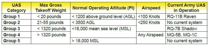
A drone is an Unmanned Aerodynamic System (UAS). There are different categories based both on weight and on the number of rotors and wing-rotor configuration. Based on flight system there are four categories: a multiro- tor, a single rotor, a fixed wing and a fixed wing hybrid VTOL drone. Based on weight there are 5 categories classified by the US Department of Defense (DoD) (Fig. 1). If even one of the aspects of a drone falls into the next cate- gory the drone is placed in that category. (Eberthart, 2017; US Army, 2010; Rennie, 2016).
The ground effect is a phenomenon that takes place when an air vehicle is flying or hovering in vicinity of another surface, as this alters the air- flow. For a single rotor UAS this takes place when the height is less than the diameter of the rotor; for a quadrotor this is when the height is less than
Ground Effect on a Landing Platform for an Unmanned Aerodynamic System 59
Figure 1: Unmanned Aircraft Systems roadmap. (Adapted from U.S. Air Force 2010.)
twice the diameter of the rotor. Ground effect impacts flight stability (alti- tude and stability control) and thrust production, thus influencing the power requirements (Tanabe et al. 2018; Tanabe et al. 2021).
In general terms, distortion due to local surfaces is observed in three situ- ations. When the device is hovering in ground effect of a surface below, the aerial flow is so that there is an increase in thrust. This allows for power requirement reduction of up to 26% compared to out of ground effect. This percentage is not the same in all previous studies. However, in ground effect the altitude and stability control are strongly reduced. This is also what cau- ses take-off and landing issues. The ground effect lessens as the forward speed increases (Bernard et al. 2017; Kan et al. 2019).
When it flies close enough to a side surface, it will cause a momentum, due to a change in air pressure around the rotors on one side of the drone. The drone is at risk to tilt towards the wall and get sucked towards it.
When it flies close enough to an upper wall, the low-pressure zone on the upper side of the rotor expands, causing a sudden increase in thrust, leading it to be sucked towards the upper wall and collide with it.
The factors that play part of this effect are multiple and intertwined, thus complex. All objects which have an influence on the airflow around the rotors can play a part on the ground effect. Thus, the amount of rotors and the gaps between them and the relative height of the drone may have an influ- ence. Differences in the shape of the objects/surfaces around may influence the effect as well, yet there has been done insufficient research to substantiate this line. The shape of the blades and the airframe of the drone plays a part too, but these factors also are still being explored (Kan et al. 2019).
In commercial UAS’s issues related to ground effect are mediated by softw- are. The drone is programmed so that it will stay out of ground effect (with a lower surface), making use of a camera/reflector to calculate the distance. Staying away from the upper- and sidewalls is up to the user. The airframe of a drone is also designed in such a way that it has minimal effect on the airflow of the rotors.
Because of this software restriction we used a non-commercial, self- assembled drone build for fpv (First Person View) racing purposes. This drone was chosen because it does not have any safety limitations (that influence test results) like commercially available drones.
In this paper only the ground effect of a lower surface on a quadrotor UAS will be tested. The thrust will be compared for different surfaces. From previous studies we take that battery life and thrust is directly linked and
proportional, hence exploiting the ground effect for flying could lead to pro- longed battery life. However, being within ground effect comes at the cost of control. Therefore, a landing platform with reduced ground effect might be beneficial.
We have not been able to find any prior research on the textures or mate- rials of landing platforms used for UAS’s or helicopters and how it would influence the landing. Therefore, researching this and its connection with the ground effect could lead to more stable landing of the aircraft.
A current landing platform is a horizontal space, away from turbulent areas (such as near a taxiway), at least the size of the diameter of the largest helicopter to be landed there. It is a landing space that minimizes turbulence. With a maximum slope of 3%, that tries to drain as much water without overriding this threshold.
These values can be less strict for certain classes of helicopters. For landing platforms in urban areas, the siting is extensively researched. Making use of CFD or a wind tunnel and the most common weather/wind patterns, the best placement for the landing pad, considering the buildings surrounding it, is checked (Smith & Hackett, 2017).
External wind streams due to wind and weather, but also due to certain rooftop exhaust sources, are an important factor for landing pads, especially within cities. In cities there are additional requirements to be accounted for, such as noise and downwash generated by the aircraft.
The above considerations lead to the following hypotheses: The ground effect will be reduced above a grid surface, compared to a solid surface, which will therefore increase stability during the landing.
(The value of ‘no surface’, is to state that the ground effect takes place and is therefore purely for reference.)
If the grid is close above a solid surface or if there are sidewalls below the grid, the ground effect will increase, reducing stability.
MATERIALS AND METHODS
Therefore, we will test different textures for a landing platform to see whether it affects the ground effect and thus the stability of the landing. Following textures will be compared:
No surface
A smooth horizontal surface (plate of 650 by 650 mm)
A grid with hexagon cut-outs, suspended in the air (plate of 650 by 650 mm and cut outs with a radius of 17, 32 mm)
A grid, with the same cut-outs, at 6 cm above a solid surface We will test the thrust level between the different surfaces, assuming that, if the ground effect is reduced, the stability will increase.
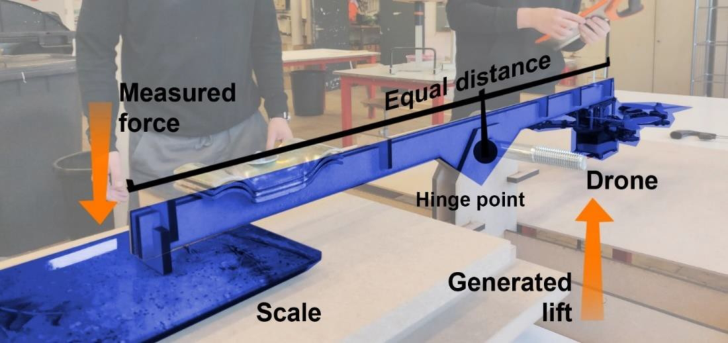
The area of the plate is large enough. 140 + 2*(2*125) = 640 mm The drone is held by a contraption (Fig. 2). The arm of the contraption is connected to a scale. When drone is power off, we made use of counterw- eights so that the arm of the contraption was in a horizontal position, thus in balance. The thrust of the drone is measured by this scale. The scale has
Ground Effect on a Landing Platform for an Unmanned Aerodynamic System 61
Figure 2: Picture of the set-up for the thrust-test.
an accuracy of 1 gram. Seven values will be recorded for each surface. If the thrust increase for the test-surface differs greatly from the solid surface (H0), we can assume that the ground effect is reduced. If the ground effect is reduced, the stability of landing should be increased.
The drone used is a non-commercial, custom assembled one, as this does not have software implemented boundaries considering ground effect of a lower surface. It has 4 rotors with triple blades with a diameter of 125 mm. The total weight of the drone itself is 399 grams.
The drone was powered by a bench power supply which delivers 12V at a maximum of 30A. We opted for a fixed power supply due to the unstable nature and power levels of the original lithium polymer battery pack.
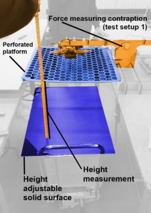
Additionally, to this we tested the minimal distance needed between the grid and the surface below for the air to flow through to minimize introduced turbulence. The drone is hovering in its contraption above the grid surface (Fig. 3). The solid surface is held below the grid and moved downwards with increments of 50 mm. The contraption is turned 180
, so that the side walls are no longer there.
Figure 3: Picture of the set-up for the distance-test.
This distance was then rewritten to diameters of the rotor, as this proved to be a reliable way of formulating for other formula’s, since the distance and area of the landing platform will differ depending on the size of the drone.
Results
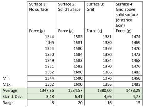
In Figure 4, the phenomenon of the ground effect is clearly shown. The thrust force is less for the no surface than for the solid surface, with a difference of 14,94%, indicating that the ground effect takes place. The thrust force of the grid is less than that of the solid surface, with a difference of 12,91%. The difference between a grid and no surface is that of 2,33%.
Figure 4: Results for the thrust-force for the four different surfaces. 7 values for each surface.
Ground Effect on a Landing Platform for an Unmanned Aerodynamic System 63
With the purpose of evaluating the significance of the data collected, the p value of each surface in comparison to the mean of the ‘no surface’ value was calculated. This shows how closely the results from the surfaces experiments are from the no surface trials.
From these results can be assumed that the thrust force, measured by the scale, differs significantly from one another.
Further, the means of the surfaces have been compared to the solid surface data.
Eventually, the ‘grid above solid surface’ has been compared to the ‘grid above air’ surface.
There is a clear significance between grid with and without a solid surface beneath. All the P values have been calculated with the T-TEST function in Excel.
In accordance with the percentages previously calculated, there is a substantial difference between thrust force in each case.
If the distance between the grid and a second surface is too small, then the thrust force will increase by 6,33% compared to a sole grid. Which makes it only 7,55% more efficient than a solid surface.
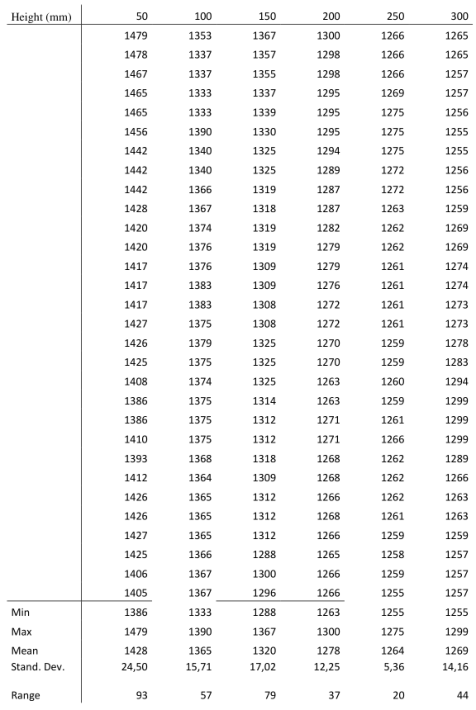
Figure 5: Results for the thrust-force according to the distance between the grid and a lower solid surface. 30 values through time for each distance.
In Figure 5, thirty thrust values are noted for each distance. We will not compare it to data found in the thrust-test, as each run had a dif- ferent spectre. At this distance the effect of the second, lower surface is nullified.
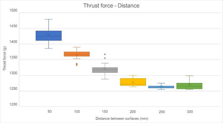
We express this value in the amount of rotor blade diameters. With the diameter of the rotor blades (db) being 125 mm, this gives the following formula: Distance min = d/db * db = 250/125 * db = 2 db So, the minimal distance is 2 times the diameter of the rotor blades. The trend is visible in Figure 6. It hints towards a logarithmic trend. The trendline has a R2 of 0,97.
The significances of trust force data of the different distances support these claims.
Ground Effect on a Landing Platform for an Unmanned Aerodynamic System 65
Figure 6: Boxplot of the data from Figure 5.
DISCUSSION
Not all our tests provided usable data. This was due to multiple reasons, including: technical problems with controlling the drone thrust, unstable power levels and different uncontrollable variables like the internal chemi- stry of the original battery pack. Therefore, we did the test at maximum power level. For the same reason we replaced the battery with a lab power supply. Even though we took these measures, the power used by the drone fluctuated between tests. Therefore, we do not directly compare data from the thrust-test with data from the distance-test.
Take note that because of the rather low number of data, the percentages are not to be taken too strictly. However, the trendline does show a significant trend.
In the results for surface 4, the thrust values are lower than above a solid surface. However, the stability of the drone was visibly worse. That is why this type of surface should be avoided. The slight reduction in theo- retical ground effect, does not make up for the increase in turbulence. This turbulence is due to the air current interacting with the surface below.
The fact that the thrust-value is lower above this surface than above a solid surface, while there was visibly more turbulence, was a result we did not expect to see. In our other tests, ones of which we did not present our results due to insufficient data, this was the opposite case. There some test runs showed a higher value for a double surface than a solid surface. More tests comparing the solid and double surface are required to make a grounded statement about this difference in thrust level. Nonetheless, surface 4 is not an interesting choice for a landing platform.
We measured the distanced at increments of 50mm. We did not let it incre- ase gradually, for the readings on the force were not stable enough to get a accurate enough graph. We opted for increments of 50mm. Further, more accurate testing would be interesting for future research.
We formulated the minimal distance between the two surfaces in diameters of the rotor blade as this proved to be a solid measure for other surfaces interacting with the ground effect. In future tests could be checked whether these are in fact related.
The data for the distance of 300 mm does not follow the trend, which is unfortunate as this seemed to be the point where the trend is to stagnate. The reason for the extra turbulence during the testing of this distance is unclear.
The range for the different distances shows a high fluctuation and no trend. This was unexpected, as we assumed it would decrease as the distance increased, for the turbulence is greater when the second surface is closer.
Therefore, we propose following requirements for the landing platform: a grid surface that is at least twice the diameter of the rotor of the drone above the surface below. The grid surface should have an area 2 times the rotor on each side of the largest UAV to land there. Our proposed solution for an optimal landing platform (that would need to be confirmed in further testing and research) is a two layered approach consisting of a grid surface (creating minimal turbulence, thus ground effect) an air gap without walls (so the excess airflow can escape without creating extra turbulence) and a bottom layer that is distanced far enough from the top grid surface (for our drone with a propellor diameter of 125mm) this gap should minimally be 250mm.
CONCLUSION
The ground effect is reduced above a grid surface, compared to a solid surface, by about 12,91%. If the grid is too close to a solid surface below, or has sidewalls below the grid, the effect is lessened. The ground effect is then only 6,33% lower compared to a solid surface. The air gets trapped within that space and bounces back in the rotors, altering the airflow. The stress put on the grid is also to be taken into account.
Therefore, there needs to be at least 2 times the diameter of the rotor between the grid and the surface below.
Assuming that a reduced thrust level due to ground effect leads to a more stable landing, we can conclude that a grid platform is a promising option for an improved landing platform.
We formulated the minimal distance between the two surfaces in diameters of the rotor blade as this proved to be a solid measure for other surfaces interacting with the ground effect. In future tests could be checked whether these are in fact related. An approximation of a desirable landing platform for our 125mm-diameter rotor propellor is attached.
Ground Effect on a Landing Platform for an Unmanned Aerodynamic System 67
Relevant further research on this topic might be a more detailed study on the minimal distance between the grid and the secondary surface, testing other drag- reducing surfaces. Testing the actual stability of the aircraft when landing. Testing the influence of different power levels on the ground effect and whether or not there is a linear or exponential correlation between these variables.
REFERENCES
Abdullah, Q. A. (2022). Classification of the Unmanned Aerial Systems. PennStage College of Earth and Mineral Sciences. https://www.e- education.psu.edu/geog892/node/5 Bernard, D. D. C., Riccardi, F., Giurato, M., & Lovera, M. (2017). A dynamic analysis of ground effect for a quadrotor platform. IFAC-PapersOnLine, 50(1), 10311– 10316. https://doi.org/10.1016/j.ifacol.2017.08.1500 Cont Bernard, D. del, Giurato, M., Riccardi, F., & Lovera, M. (n.d.). Ground effect
analysis for a quadrotor platform. Domel, A. G., Saadat, M. et Al. (2018). Shark skin-inspired designs that improve aerodynamic performance. The Royal Society, 15. Eberhart, G. M. (2017). Modeling of Ground Effect Benefits for Multi-Rotor Small
Unmanned Aerial Systems at Hover. Garofano-Soldado, A., Sanchez-Cuevas, P. J., Heredia, G., & Ollero, A. (2022). Numerical-experimental evaluation and modelling of aerodynamic ground effect for small- scale tilted propellers at low Reynolds numbers. In Aerospace Science and Technology (Vol. 126). Elsevier Masson s.r.l. https://doi.org/10.1016/j.ast.2022.107625 He, X., & Leang, K. K. (2019). DSCC2019-9025 A NEW QUASI-STEADY IN- GROUND EFFECT MODEL FOR ROTORCRAFT UNMANNED AERIAL VEHICLES. Herkenhoff, B., & Hassanalian, M. (2022). Potential Applications and Integration
of Ground Effects on Amphibious Drones: Shearwaters and Bioinspiration. AIAA AVIATION 2022 Forum. https://doi.org/10.2514/6.2022–3814 Kan, X., Thomas, J., Teng, H., Tanner, H. G., Kumar, V., & Karydis, K. (2019). Analysis of Ground Effect for Small-Scale UAVs in Forw- ard Flight. IEEE Robotics and Automation Letters, 4(4), 3860–3867. https://doi.org/10.1109/lra.2019.2929993 RA3531 - Helicopter Landing Site - Physical Characteristics, (2018). Smith, A., Bell, A., & Hackett, D. (2017). TRADE-OFFS IN HELIPAD SITING & DESIGN. Rennie, J. (2016, November 8). Drone types: Multi-rotor vs Fixed-wing vs Single
rotor vs Hybrid VTOL. https://www.auav.com.au/articles/drone-types/ Tanabe, Y., Sugawara, H., Sunada, S., Yonezawa, K., & Tokutake, H. (2021). Quadrotor drone hovering in ground effect. Journal of Robotics and Mechatronics, 33(2), 339–347. https://doi.org/10.20965/jrm.2021.p0339 Tanabe, Y., Sugiura, M., Aoyama, T., Sugawara, H., Sunada, S., Yone- zawa, K., & Tokutake, H. (2018). Multiple rotors hovering near an upper or a side wall. Journal of Robotics and Mechatronics, 30(3), 344–353. https://doi.org/10.20965/jrm.2018.p0344 The Sciences. (2005, September 19). How do dimples in golf balls affect their flight?
https://www.scientificamerican. com/article/how-do-dimples-in-golf-ba/ U. S. Army. (2010). Unmanned Aircraft Systems Roadmap 2010-2035.
LISTED IN THE AHFE DIGITAL BOOKSTORE CATALOGUE
Explore the complete digital volume
Human Factors in Robots, Drones and Unmanned Systems
Read this individual research paper free through the original publisher, or explore the full digital proceedings book.
ISBN 978-1-958651-69-8
Explore this ISBN in the AHFE Bookstore ↗Listed in the July 2026 bookstore catalogue; search by ISBN to confirm current availability · Digital book purchase optional