The popularization of geodesic domes as a living space was one of R. B. Fuller's challenges for modern mankind. The search for a technology that can optimally satisfy this desire in a society living in a temperate climate has become the goal of the structural studies described in this study. The technological solution of the layer of sandwich panels depends on the adopted discrete division of the polyhe-dron surface. Due to the relatively simple shape of the element, the dodecahedron was adopted as the basic body. The designated triangular elements constitute the initial shape of the basic element. Analysis of the edges of connections of triangu-lar panels forms the resulting shape of the spatial solid of the component element. The use of thin GRC concrete slabs in the load-bearing layers allows it to work with metal edges around the perimeter of the panel. The solution of the geometry of the structure nodes is of decisive importance for the technology of assembling the panels into a compact arrangement of the spherical shell. In order to assess the technical value of the created model, an original measurement system was de-signed based on statically operating measurement poles. The system of mechani-cally adjustable measuring poles serves at the same time adjustable load, forced deformation and protects the model in case of loss of stability during strength tests. The research experience obtained on the initial model will be used in further detailed testing of the sandwich panel roofing system described in the paper.
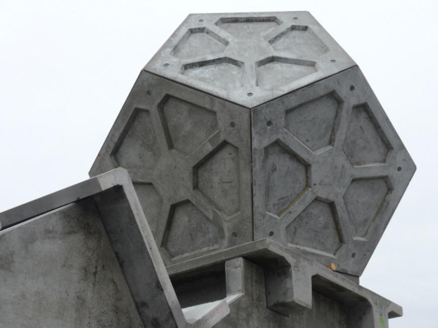
Since the Expo Dome in Montreal 1967, geodesic domes have become part of the modern built environment. As small architectural forms, geodesic covers of recreational houses occurred in thousands of copies on the slopes of the hills and valleys inhabited by humans. The dominant technology used in the implementation of these projects, however, were bar structures on the spherical surface. Panels with different degrees of transparency of thermal insulation were used as the filling in these ultra-light constructions. The authors of the paper already have an experience with the implementation of panel structures composed of thin-walled concrete slabs (Fig. 1). As a result of their research, a structure was proposed in which the reinforcement of the panels was provided by ribs embedded in the plate. These ribs divided the polygon faces of the dodecahedron form into triangles. In this particular case, the resulting structure (the tank) houses a retention reservoir on the roof of the building. Below the polyhedron of the tank, a multi-level parking lot for passenger cars is assembled from prefabricated elements.
Figure 1. The panel structure composed of thin-walled concrete slabs
The results of this research have led to certain general conclusions. Most importantly, from the perspective of the topological analysis of the discrete surfaces, these discrete surfaces can assume a dual structural function. Traditionally, structural bars have been located along great circles. By breaking the material continuity of great circles in the mesh nodes, structural triangles in the geodesic mesh are obtained. The problem of a discontinuous concrete coating can be solved by fusing its triangular tails with metal edges. The thin-walled edge profiles are thus stiffened and protect the thin GRC boards against brittle fracture. The two-sided use of the concrete coating affects the spatial stiffness and allows the space inside the panel to be filled with insulating material. In the absence of objective tools for strength analysis, testing full-scale models is the surest way to confirm the adopted technological solutions for the design.
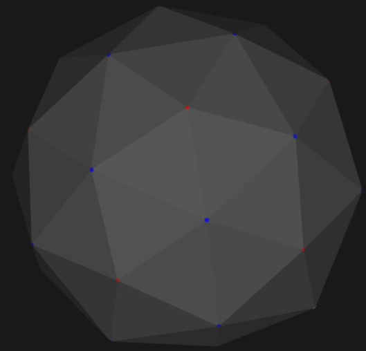
Figure 2. Dodecahedron surface triangulation DIVISION OF A REGULAR DODECAHEDRON INTO TRIANGULAR PANELS
The basic hemispherical shape was adopted as the form of the spherical roof covering. The constituent elements of the dodecahedron are regular pentagons and hexagons. By marking the midpoint on the surface of the sphere, the midpoint of the triangular
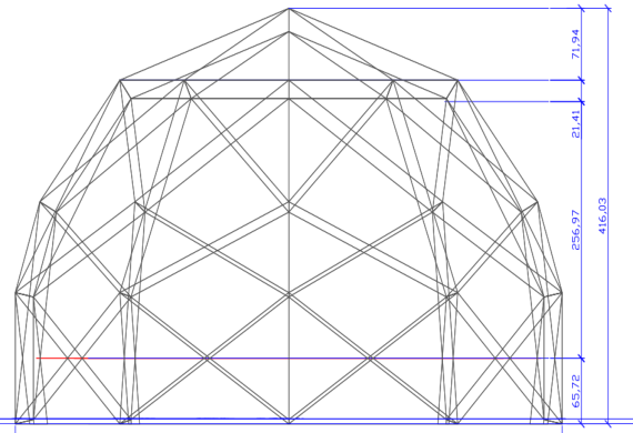
Human Interaction & Emerging Technologies (IHIET-AI 2022) Artificial Intelligence & Future Applications https://openaccess.cms-conferences.org/#/publications/book/978-1-7923-8989-4 division was obtained. As a consequence of this division, the contours of the geodesic shell with triangular panels were formed. These second-division panels – in the shape of isosceles triangles – were formed above the perimeter of the shell’s base. A tensioned ring was located at the lower edges of the second type panels, which maintains the stability of the entire shell. At the same time, the creation of a plinth layer in the coating, by raising the center of the sphere by approx. 70 cm, enables the use of the functional inner surface in a direct position at the cover structure. This two- element system of panels provides the possibility of shaping the layout of the entire shell, however, not taking into account the possibility of entering the structure. Until the opening for the entrance door is solved, a circular opening in the first row panel will be used, covered with an acrylic glass hatch. An important aspect of modeling the panel shell is the adoption of the dimensions of the edge of the model, which is intended to be a foldable structure. In order to enable transport on trucks as well as the possibility of assembly without the use of construction equipment, the basic dimension of the edge was assumed to be 2.0 m. This assumption implies the size of the designed model with a radius of approx. 3.0 m and a base diameter of approx. 6.0 m for the interior dimensions of the model. Such a size of the body of the research model enables tests to be carried out in laboratory conditions. The low weight of both the panels and, consequently, the entire coating allows it to be mounted directly on the industrial floor of the research laboratory. Due to the envisaged tests in open climatic conditions, it is also proposed to base the model on cylindrical alloy foundations buried in the lawn of the university campus.
Figure 3. Arrangement of a vertex on the surface of a sphere
Figure available in the original PDF paper.
SHAPING THE STRUCTURAL ELEMENTS OF A
MULTILAYER PANEL
The technological premise for the model structure was the use of a composite structure, where the panels of the panel covering would be made of a thin layer of GRC concrete reinforced with fiber. The initial thickness of the concrete slab was determined to be 1.5 cm. Ribs will be formed on the edges of the panel to connect with metal profiles. The joining of the plate ribs with the metal edge will be implemented by means of a series of metal pins concreted in the rib. The metal profiles on the edges of the panel are bent from 1.5 mm thick stainless steel. Due to the complicated shape of the panels, a CAD model was built, used by computer- controlled bending machines to maintain the minimum tolerance of the dimensions of prefabricated elements. The gap between the edge of the concrete rib in relation to the plane of the metal profile breaks the continuity of the coating and protects it against mutual crushing of the concrete edges at the joints of the panels. The use of edge profiles reinforces the panel structure and at the same time constitutes a plane for joining the panels into one system. It is planned to use bolts that will join the planes of the metal edges. Mechanized fasteners closed from the inside of the panels are envisioned as the ultimate solution for this design, and their tests are underway. An important parameter that makes it difficult to obtain a satisfactory solution for this connection is the dimensional tolerance when assembling a set of panels in one structure.
To determine the solid geometry of the component panel, it is important to define the thickness of the entire layer system. In addition to the structural aspects, the thermal insulation properties of the covering should be taken into account here. The initial insulation calculations gave a layer thickness of a standard insulation material (0.035 W / m K) of 23 cm. Based on this calculation, the total thickness of the panel was adopted as 25 cm, which also gives sufficient stiffness of the entire layered coating of the model. As a result of the optimization analysis, the construction height of the metal edge strip is 13 cm. An important technological issue is the formation of the apex connections of the edges of the metal panels. As the angle of connection of the edge axis does not exceed 60 degrees, the intersection of the plates can be treated as an acute angle. In this geometric shape, it is advisable to cut the edge of the knot and close it with a sheet perpendicular to the bisector of the corner. Determining the position of the closing plate poses a research problem related to the sealing of the panel coating and the aesthetic finish of the panel joints in their upper layer. The panel shell shaped in this way does not have a continuous steel skeleton, and therefore its spatial stiffness is determined by the interaction of the plates of the connected panels. The homogeneous panel coating reduces the concentration of internal forces and creates conditions for the redistribution of stresses over the entire spherical surface. The outer surface of the panels, apart from the structural one, has two other important functions. One of them is providing the outer surface of the building. Due to its spherical shape, the surface is a roof in its upper part and a wall in its lower part. The smooth change of this function is made discrete by the triangular form of the cover panels. The second additional function is external insulation against rainwater flowing down this surface. The required degree of tightness is greatest on the upper
Human Interaction & Emerging Technologies (IHIET-AI 2022) Artificial Intelligence & Future Applications https://openaccess.cms-conferences.org/#/publications/book/978-1-7923-8989-4 pentagon of the solid’s body. The tightness of the outer surface in the lower ring of the coating surface is no longer required due to the decreasing angle of inclination of the panels. A significant problem requiring a technical solution is the geometrical shape of the nodes in the panel connections. They no longer perform a structural function, but their design has a significant impact on the tightness of the entire coating. As they represent the meeting point of the edges of five or six panels, it is difficult to expect an ideal solution. Therefore, the best shape at this point is a polygonal hole. Covering this opening with a metal cover may fulfill both an aesthetic function and ensure the tightness of the coating.
SEARCHING FOR STATIC PROPERTIES OF A
PANEL COVERING Testing the stiffness of a panel shell requires a specific design of a load system that perfectly simulates the actual shell loads. The basic load constantly acting on the coating is its own weight. The uniform distribution of this load on the spherical shell causes compressive forces in the meridional direction. In the latitudinal direction, compression is present at the top of the shell, to a radial angle of about 45 degrees. Below this angle, there is a tension, the significant value of which should be transferred by the circumferential lower ring.
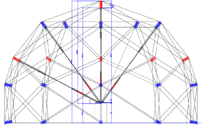
Figure 5. Measuring poles in the structure space The resistance to the dead weight will be tested in the model already during the assembly phase of the spherical shell. An annular assembly is foreseen, starting with
Human Interaction & Emerging Technologies (IHIET-AI 2022) Artificial Intelligence & Future Applications https://openaccess.cms-conferences.org/#/publications/book/978-1-7923-8989-4 the support ring. Panels of the second type will be installed in the first row. First-row triangular panels rest on their edges. From the top, the arrangement of panels forms a regular pentagon. Due to the installation height, this part of the structure can be mounted with a small crane. However, this process requires a high degree of accuracy in the prefabricated components. An important assembly parameter is to maintain the radial distance of the geometrical nodal points of the shell in relation to the geometric center of the sphere. For this purpose, adjustable steel poles have been designed that are used for many functions in the model studies. During the assembly of the panels, the poles provide point support for the corners of the panels. The continuous adjustment of the pole length allows imprecisions to be taken into account during assembly. Once the panel coating system has been assembled, the poles are the original measuring tools, which have been used particularly for conducting research on the strength properties of the coating. Force gauges mounted in the axis of the poles enable the introduction of measuring loads that are acting perpendicular to the surface of the coating. An important premise in mounting the pole is to hook it into the geometric center of the shell sphere. The technical implementation of this support requires an elongated pedestal with handles on the pile head. The forces introduced along the poles induce shell deformations that can be measured with a simple laser device. The poles also act as a temporary support in the event of a breakdown of the panel arrangement under test loads. In this case, the metal edges of the panels rest on the pole collar. The method of loading carried out in the model depends on the geometric position of the poles. The first test will be the nodes in the upper part of the shell due to the snow loads that may occur there. Asymmetric pole arrangements will be used to simulate the horizontal wind load. Additional tests should cover the surface of the concrete layer of the panels and their edge strips. Using strain gauge measurements, the contact surface of the GRC ribs with the surface of the metal edges will be examined. The expected composite effects should have a decisive influence on the load-bearing capacity of the entire panel shell.
CONCLUSIONS
The tested system of sandwich panels is an interesting alternative to the commonly dominant frame designs in structural systems of bar shells. The use of GRC concrete in external coatings ensures durability and resistance of the covering to the effects of external environmental factors that may cause corrosion in the roofing components. Despite the use of concrete as a structural material, the structure maintains lightness, and can be assembled without the use of heavy machinery. The low weight of the structure of this form of roofing allows it to be used in less accessible mountainous areas. Multiple assembly and disassembly of the structure is possible on account of the structure’s mobility without incurring high costs for dismantling and the disposal of building materials. The described triangular model of panels can be designed and tested for geodesic domes with larger spans, after increasing the structural thickness of the panels and strengthening the edge joints. The proposed method of
Human Interaction & Emerging Technologies (IHIET-AI 2022) Artificial Intelligence & Future Applications https://openaccess.cms-conferences.org/#/publications/book/978-1-7923-8989-4 measurements with the use of poles in a radial arrangement enables testing in laboratory conditions and in the external environment with the compliance of safety rules, even in the event of failure of panel connections. Further research and implementation require joining the panels and functional solutions for modifying the covering by openings for doors and windows illuminating the interior of the building.
REFERENCES
Baldwin, J.: Buckyworks: Buckminster Fuller's Ideas for Today, New York 1996 Bober, W.: Geodesic domes in built environments. W: Advances in Human Factors in Architecture, Sustainable Urban Planning and Infrastructure : proceedings of the AHFE 2020 Virtual Conference on Human Factors in Architecture, Sustainable Urban Planning and Infrastructure, Springer, cop. 2020. s. 105-111 Bober, W., Oktaba, M.: Influence of R. B. Fuller on the development of tensegrity
art by K. Snelson. W: Proceedings of the IASS Symposium 2018 : Creativity in Structural Design, July 16-20, 2018, MIT Fuller, R. B.: Explorations in the Geometry of Thinking, New York 1979, Macmillan
Read this individual research paper free through the original publisher, or explore the full digital proceedings book.
ISBN 978-1-7923-8989-4
Explore this ISBN in the AHFE Bookstore ↗Listed in the July 2026 bookstore catalogue; search by ISBN to confirm current availability · Digital book purchase optional