George Boiadjiev, Tony Boiadjiev, Kamen Delchev, Ivan Chavdarov, Rumen Kastelov (2021). Temperature control in robotic bone drilling process. In: Human Systems Engineering and Design (IHSED2021): Future Trends and Applications. AHFE Open Access, vol. 21. https://doi.org/10.54941/ahfe1001148
The orthopedic manipulation “bone drilling” is the most commonly used in the surgical treatment of bone fractures. The bone drilling process is characterized with a set of input and output parameters. The first ones define the conditions of the process execution and the second ones determine the outcome. The input parameters as feed rate [mm/s] and drill speed [rpm] have the most importance for the outcome, namely thermal and mechanical damages of the bone tissue.Many scientific researches related to the input parameters influence to the bone drilling process are published. The purpose is to find such an input parameters combination which is able to guarantee optimal result concerning the outcome parameters of the bone drilling process.The difference between the experimental results of many studies appears and even becomes bigger for the sake of wide variety of test conditions used by researchers. However, the following common dependencies stand out:-to avoid thermal osteonecrosis the drilling process must be executed with possibly maximal feed rate value together with possibly minimal drill speed value. -to avoid traumatic osteonecrosis the drilling process must be executed with possibly minimal feed rate value and possibly maximal drill speed value.So that the requirements concerning the drill speed and the feed rate values are contradictory and in the same time such values must be maintained during the bone drilling process aiming to obtain the optimal results. In manual drilling these parameters are controlled by the surgeon on the base of his practical experience. But the control of these parameters and the achievement of their optimal values can be successfully realized only under its robotized execution.Feed rate control during an automatic bone drilling process using an orthopedic drilling robot ODRO has already been introduced in our previous publications. The drill speed control is the next step in the development of ODRO.During bone drilling a significant amount of already done mechanical work directly converts into thermal heat elevated at the tool – bone interface. Since the critical temperature for thermal osteonecrosis is the most rigorously defined to be 47°C, the purpose of drill speed control during bone drilling process is to maintain the temperature below this critical threshold.Currently drill bit rotation in our case is realized on the base of MAXON BLDC controller/driver. With this type of controller, the motor speed is controlled entirely by hardware. It not allows software implementation of an algorithm for controlling the speed of the motor. The created and developed algorithm as well as the obtained and presented experimental results have a purpose to demonstrate the abilities of the controller TMCM 1630 for drill speed control during bone drilling process in dependence on the data characterizing the temperature deviation.This work presents basic characteristics of ODRO as well as a new drill speed control algorithm. It is one more additional step for improving the functionality of ODRO together with feed rate control during drilling and various specialized working regimes.
Human Systems Engineering and Design (IHSED 2021) https://openaccess.cms-conferences.org/#/publications/book/978-1-7923-8987-0
INTRODUCTION
The purpose of the robot application in surgery practice is to improve the accuracy and the precision of the executed manipulations. Some robotized systems are developed and applied both in the general surgery and the orthopedic surgery (Beasley 2012, Hoeckelmann et al. 2015). Still robots have little implementation in the orthopedic surgery. One of the reasons is they are much expensive. Moreover, they insist maintenance, which is very specific as well as special education of the surgeons. The recent tendency is creation of robots for concrete orthopedic operations. The purpose is to simplify the mechanics as much as possible. As a result, Handheld Robotized Systems appear (Boiadjiev et al. 2020). The handheld robotized systems correspond to the definitions of robot totally or in some extent and the term “robotic surgery” has a definition (Herron, Marohn 2008).
The handheld robotized systems try to achieve the accuracy and precision like the stationary multifunctional robots. They are able to work without intraoperative navigation and pre-operative planning. Also, they are cheaper and allow easy maintenance and usage.
Currently on the market and in orthopedic surgery practice it is available:
- SMARTdrillR orthopedic handheld robotic drilling device. This system is developed by “Smart Medical Devices Inc.”, US. It is able to measure in real time the already drilled depth and to minimize the plunge behind the far cortex (SMART Medical Device Inc. Website). Two motors are incorporated - for rotation and for translation of the drill bit. The thrust force in not under control. The stop of the drilling is not automatically. The decision for that is in the surgeon by monitoring the displayed data, which leads to possible error for the sake of subjective factor. No considerations and data for overheating problem prevention are presented.
- IntelliSense orthopedic surgical drill device That device is created by “McGinley Orthopedic Innovations”, US (McGinley Orthopedics website). It has two working regimes: conventional and bicortical. According to the definitions the device it is not a robot. It has only one actuator. However, it is able to give information in real time for drilled depth and for far cortex end. As disadvantages, there is no control of thrust force and that remains the surgeon responsibility on the base of its practical skills. The overheating problem is not even considered.
The DRIBON Handheld Robotized Systems (Louredo et al. 2012) is still under development. It works only in the case of bi-cortical drilling especially for precisely registration the bone end and automatically stops. The control algorithm uses error analysis of feedback position. Experimental results are reported for bi-cortical drilling of caw bone showing the time of the process over 400 s. The result is high temperature, which has to be avoided in such manipulations.
Human Systems Engineering and Design (IHSED 2021) https://openaccess.cms-conferences.org/#/publications/book/978-1-7923-8987-0
ORTHOPEDIC BONE DRILLING ROBOT. BASIC CHARACTERISTICS Our Orthopedic Drilling Robot ODRO (Boiadjiev et all. 2020) has two modules – control and executive. The drill bit rotation (0-1000 rpm) is realized by BLDC motor EC-4-pole 30 with reduction assuring 1.66 Nm. The linear displacement (0-100 mm) is realized by step motor 43000–17 applying force up to 120 N. The velocity range is 0-9 mm/s. Force sensor LMB-A-200 N (KYOWA) realizes feed-back with measurement up to 200 N. The control system is designed with the help of the controller TMCM-1110.
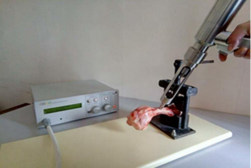
The drilling execution (see Figure 1) starts and prolongs only when the operator holds the start button pressed. If the start button is released, the operator (surgeon) may stop the drilling. The drilling continues if the button is pressed again. After that, the drill bit returns to its initial state automatically. During the manipulation, the surgeon assures firm contact with the bone.
Our robot can work in two regimes (Boiadjiev et al. 2020): “hand” or “automatic”. It works as a usual device in “hand” mode. The automatic mode has three sub-modes: Fixed depth - preliminary set depth of the hole in mm; Cortex I – drilling of near cortex; Cortex II – drilling of both cortices. The latter mode (Cortex II) in turn supports three sub-modes. The surgeon chooses and sets needed modes with the help of 4 buttons and a potentiometer. In real time, a display shows information for the process duration. The accuracy is 0.1 mm. The displacement is up to 100 mm.
Figure 1. Setup of bone drilling execution.
Human Systems Engineering and Design (IHSED 2021) https://openaccess.cms-conferences.org/#/publications/book/978-1-7923-8987-0
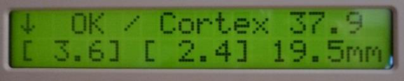
When the process is finished, information appears on the display (see Figure 2). The second displayed row of Figure 2 means the Cortex I and Cortex II thickness as well as the hole depth for bicortical drilling.
Figure 2. Information displayed after “Cortex II Full Drill” mode.
THE DRILL SPEED CONTROL DURING BONE DRILLING PROCESS Many scientific researches related to the input parameters influence to the bone drilling process are published. The publications indexed in SCOPUS are over 3000 since 2000 (Jamil et al. 2020. For experiments, Computer Numerical Control (CNC) machines are used (Wang et al. 2014, Pandey and Panda 2015, Karaca and Aksakal 2013).
The difference between the experimental results of many studies appears and even becomes bigger for the sake of different conditions of tests concerning the diameter and the type of the drill-bit, rotation velocity, feed rate and kind of bone type (Lughmani et al. 2015). However, the following common dependencies stand out: The feed rate increase leads to:
- drilling time interval decrease – reduction the heat generation and limitation the temperature arising during drilling (Augustin et al. 2008, Chen et al. 2016), i.е. the risk of thermal osteonecrosis becomes smaller; - thrust force increase - applying of bigger thrust force makes higher the risk of bone damage (traumatic osteonecrosis) (Lughmani et al. 2015). The drill speed increase leads to:
- temperature increase (Augustin et al. 2008, Chen et al. 2016, Hou et all. 2015), i.е. the risk of thermal osteonecrosis becomes bigger;
- thrust force decrease (Lughmani et al. 2015), i.е. the risk of bone damage (traumatic osteonecrosis) becomes smaller. Summarizing, to minimize the heat generation during drilling (to avoid thermal osteonecrosis) the drilling process must be executed with possibly maximal feed rate value together with possibly minimal drill speed value. For avoidance the traumatic osteonecrosis
Human Systems Engineering and Design (IHSED 2021) https://openaccess.cms-conferences.org/#/publications/book/978-1-7923-8987-0 the drilling process must be executed with possibly minimal feed rate value and possibly maximal drill speed value.
So that the requirements concerning the drill speed and the feed rate values are contradictory and in the same time such values must be maintained aiming to obtain the optimal results. This problem can be solved by simultaneously controlling the speed and the feed rate values and can be successfully realized only under its robotized execution.
Feed rate control during automatic bone drilling process by using Orthopedic Drilling Robot ODRO is presented in (Boiadjiev et al. 2021). The drill speed control during bone drilling process is the next step in the development of ODRO.
In drilling manipulations, the temperature on the tip of the drill bit arises and influences to the bone. By reports, the temperature over 47°C is considered like critical and as a result, some damages of the bone can appear, including loss of implants strength (Jamil et al. 2020).
Since the critical temperature for thermal osteonecrosis is the most rigorously defined to be 47°C (Augustin et al. 2008, Akhbar and Sulong 2021), the purpose of drill speed control is to keep precisely the reached temperature not over this critical value.
Currently drill bit rotation in our case is realized on the base of BLDC controller/driver DEC 50–5. The motor speed is controlled entirely by hardware. The realization of the idea for drill speed control insists using the different type of controller. Such type is TRINAMIC TMCM 1630. It allows for software implementation of an algorithm for controlling the speed of the motor based on data that are fed to the respective inputs of the controller.
Control Algorithm The control algorithm for motor speed is realized in dependence on data of the analog input of TMCM 1630. It is accepted that these data reflect the temperature deviation in automatic bone drilling execution for corresponding orthopedic manipulation.
The algorithm description. 1. The program monitors the corresponding digital input state. When the logical state 1 is changed to the logical state 0 the drilling starts with preliminary set maximal rotational velocity: “max_velocity”.
2. When the temperature goes over 47°C (temperature_const1) a new rotational speed is calculated; actual velocity decreases with preliminary set value “ramp_const1”. Such calculated value “Desired_vel” is set as “Target velocity”. If the temperature still keeps values over 47°C at every discretization sample then the rotational speed decreases again. The rotational speed decreasing prolongs until the minimal rotational speed “min_velocity” is reached. The level, which characterizes the rotational speed deviation, is determined by “ramp_const1”. If the temperature falls under 47°C then the rotational speed increases and the new its value is determined by the global parameter “max_velocity”.
3. When the temperature goes over 60°C (“temperature_const2”) a new rotational speed is calculated; actual velocity is decreased by preliminary set value “ramp_const2”. This calculated value “Desired_vel” is set as “Target velocity”. If the temperature still keeps on values over 60°C at every discretization sample then the rotational speed decreases again. The rotational speed decreasing prolongs until the minimal rotational speed “min_velocity”
Human Systems Engineering and Design (IHSED 2021) https://openaccess.cms-conferences.org/#/publications/book/978-1-7923-8987-0 is reached. The level, which characterizes the rotational speed deviation, is determined by “ramp_const2”. If the temperature falls under 47°C then the rotational speed increases and the new its value is determined by the global parameter “max_velocity”.
Experimental results The experiments are realized with BLDC motor MAXON EC-4-pole 30. The experimental results for the calculated velocity (target velocity) of the motor in dependence on the temperature deviation are presented in Figure 3.
Figure 3. Graph of target velocity when the temperature increases over 47°C and over 60°C.The velocity data are scaled by coefficient 10-1 and those for the temperature – by 10. The recording time is 15.391 s; the number of records is 7566.
Figure available in the original PDF paper.
The following zones can be pointed out in the graph:
- up to the record number 2202 the recorded temperature is under 47°C and the motor target velocity is 4000 rpm; - after the record number 2202 the temperature increases over 47°C and the target velocity begins decreasing; the level which characterizes the rotational velocity deviation is determined by “ramp_const1”; - record number 5063: the recorded temperature increases over 60°C; the rotational velocity decreasing goes on and the level which characterizes the rotational velocity deviation is determined by “ramp_const2”; the rotational
Human Systems Engineering and Design (IHSED 2021) https://openaccess.cms-conferences.org/#/publications/book/978-1-7923-8987-0 velocity drcreasing prolongs until the minimal rotational velocity “min_velocity” (800 rpm) is reached which occurs at record number 5419; - record number 6385: the recorded temperature is under 47°C and the target velocity takes value 4000 rpm (max_velocity). For the experiments the concrete values are used which define the maximal and the minimal velocity and must be maintained by the controller. Such values are determined by the corresponding constants. So that the velocities can be easily changed with other ones. The same is valid also for the constants characterizing the level of the velocity deviation as well as the border values characterizing the temperature increasing. The values of these constants can be precisely determined during experiments where the temperature increasing is recorded in real bone drilling so that the process be optimal from the viewpoint of temperature maintenance in limited borders.
The created and developed algorithm as well as the presented experimental results have a purpose to demonstrate the abilities of the controller TMCM 1630 for drill speed control during bone drilling process in dependence on the data characterizing the temperature.
CONCLUSIONS
The handheld robotized systems have their role and place in the orthopedic surgery practice. The precision they realize the manipulations helps to assure higher reliability of the operations and safety of the patients.
This work presents basic characteristics of the handheld Orthopedic Drilling Robot ODRO as well as a new drill speed control algorithm. It is one more additional step for improving the functionality of ODRO together with feed rate control during drilling.
By reports, the other handheld systems mentioned above can perform only bicortical drilling. ODRO together with such ability has additional working modes.
Finally, the controller TMCM 1630 incorporation in the ODRO control system can realize the drill speed control and guarantee the optimal temperature regime during the manipulation from viewpoint of control the temperature deviation in the drilling zone.
ACKNOWLEDGMENTS
Authors are thankful to Sofia University “St. Kliment Ohridski”, Dept. of Mathematics and Informatics, for the financial support.
Human Systems Engineering and Design (IHSED 2021) https://openaccess.cms-conferences.org/#/publications/book/978-1-7923-8987-0
REFERENCES
Akhbar, M.F.A., and Sulong, A.W. (2021). “Surgical Drill Bit Design and Thermomechanical Damage in Bone Drilling: A Review”, Annals of Biomedical Engineering, 49, 29-56. Augustin, G., Davila, S., Mihoci, et all. (2008). “Thermal osteonecrosis and bone drilling
parameters revisited”, Archives of orthopaedic and trauma surgery, 128, 71-77. Beasley, R.A. (2012). “Medical Robots: Current System and Research Directions”, Journal of Robotics, 2012, 1—14. Boiadjiev, G., Boiadjiev, T., Delchev, et al. (2020). “Basic Characteristics of Handheld
Robotized Systems in Orthopedic Surgery”, 28th International Conference on Software, Telecommunications and Computer Networks, 1-5. Boiadjiev, T., Boiadjiev, G., Delchev, K., et al. (2021). “Feed rate control in robotic bone drilling process”, Proceedings of the Institution of Mechanical Engineers. Part H, Journal of engineering in medicine, 235(3), 273-280. Chen, Y., Hsiao, C., Ciou, J., et al. (2016). “Effects of implant drilling parameters for pilot
and twist drills on temperature rise in bone analog and alveolar bones”, Medical engineering & physics, 38, 1314-1321. Fernandes, M., Fonseca, E., Jorge, R., et al. (2018). “Effect of drill speed on the strain distribution during drilling of bovine and human bones”, Journal of Mechanical Engineering and Biomechanics, 2, 69-74. Herron, D.M., Marohn, M., SAGES–MIRA Robotic Surgery Consensus Group (2008). “A
consensus document on robotic surgery”, Surgical endoscopy, 22, 313-325. Hoeckelmann, M., Rudas, I.J., Fiorini, P., et al. (2015). “Current Capabilities and Development Potential in Surgical Robotics”, International Journal of Advanced Robotic Systems, 12, 1-39. Hou, Y., Li, C., Ma, H., et al. (2015). “An Experimental Research on Bone Drilling
Temperature in Orthopaedic Surgery”, The Open Materials Science Journal, 9, 178- 188. Jamil, M., Rafique, S., Khan, A.M., et al. (2020). “Comprehensive analysis on orthopedic drilling: A state-of-the-art review”, Proceedings of the Institution of Mechanical Engineers. Part H, Journal of engineering in medicine, 234, 537-561. Karaca, F. and Aksakal, B. (2013). “Effects of various drilling parameters on bone during
implantology: An in vitro experimental study”, Acta of bioengineering and biomechanics, 15, 25-32. Louredo, M., Diaz, I., and Gil, J. (2012). “DRIBON: A mechatronic bone drilling tool”, Mechatronics, 22, 1060-1066. Lughmani, W., Bouazza-Marouf, K., and Ashcroft, I. (2015). “Drilling in cortical bone: A
Finite element model and experimental investigations”, Journal of the Mechanical Behavior of Biomedical Materials, 42, 32-42. McGinley Orthopedics website: https://www.mcginleyorthopedicinnovations.com/ Pandey, R.K. and Panda, S.S. (2015). “Evaluation of delamination in drilling of bone”, Medical Engineering & Physics, 37, 657-664. SMART Medical Device Inc. website: https://smartmeddevices.com/smartdrill-6-0/# Wang, W., Shi, Y., Yang, N., and Yuan, X. (2014). “Experimental analysis of drilling
process in cortical bone”, Medical Engineering & Physics, 36, 261-266.
Human Systems Engineering and Design (IHSED 2021) https://openaccess.cms-conferences.org/#/publications/book/978-1-7923-8987-0
LISTED IN THE AHFE DIGITAL BOOKSTORE CATALOGUE
Explore the complete digital volume
Human Systems Engineering and Design (IHSED2021): Future Trends and Applications
Read this individual research paper free through the original publisher, or explore the full digital proceedings book.
ISBN 978-1-7923-8987-0
Explore this ISBN in the AHFE Bookstore ↗Listed in the July 2026 bookstore catalogue; search by ISBN to confirm current availability · Digital book purchase optional